Jump to content


Photo

Aquamist Install Guide


  • Please log in to reply
26 replies to this topic

#1 Firthy

Firthy

    Super Duper Member

  • PipPipPip
  • 576 posts
  • Gender:Male
  • Location:Surrey

Posted 01 December 2019 - 07:36 PM

Hi All,

I'm going to install an aquamist system on my stage 2 SC as a full belts and braces solution to maintain power... Plus I'm frustrated with my bloody charge cooler pump as it just failed on the drive to Silverstone GP so I didn't drive it as the temps were rocketing. Very frustrating!

Does anyone have a self fit guide to install the system?

The areas I'm not sure on are where to get power from... what nozzle size to have, and how to fit it to the inlet manifold.

Any help would be very much appreciated.

Elliot

Edited by Firthy, 01 December 2019 - 07:41 PM.


#2 hairy

hairy

    Moonlander

  • PipPipPipPipPipPip
  • 5,827 posts
  • Gender:Male
  • Location:Bristol
  • Interests:cars, beer, nature

Posted 01 December 2019 - 08:02 PM

A few pointers here: https://www.saab9000...erinjection.php


#3 Co220

Co220

    Member

  • Pip
  • 41 posts

Posted 02 December 2019 - 04:04 PM

If you switch to OBD tuner pro, you will find good installation instructions in the guide.

Including the way to calculate the right injector size.


And added some pictures of the mounting of the injectors in the manifold.


540.jpg
 
540.jpg
 
540.jpg


#4 Firthy

Firthy

    Super Duper Member

  • PipPipPip
  • 576 posts
  • Gender:Male
  • Location:Surrey

Posted 08 December 2019 - 10:51 PM

Thank you very much indeed for the pics... I think my biggest challenge would be the wiring.

Any idea tips or guides on how to wire in the aquamist?

I also need to do wide band wiring as well.

Elliot

#5 FabianG

FabianG

    Member

  • Pip
  • 31 posts
  • Location:Germany

Posted 09 December 2019 - 01:23 PM

20170330_192556.thumb.jpg.4d9e6497ceae9e


Maybe this helps: https://www.speedste...&comment=131604

(its more about the OBD Pro Setup)


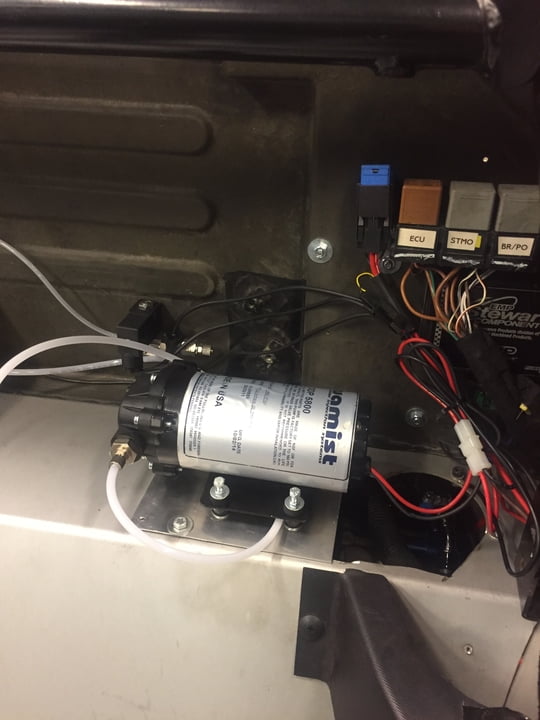
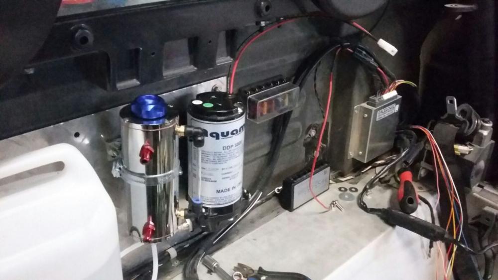
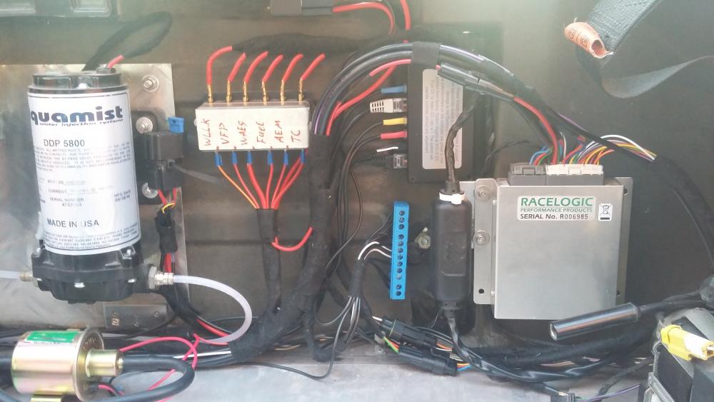
If you mount the System behind the seats, you can reach all cables from the engine bay. But you can mount it where ever you want. 

The high pressure water pump has to sit below the water tank because it cant suck water. If not possitble you can install an additional pump (the golden thing on my picture) to provide the water to the high pressure pump.

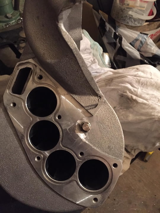
You will get the best cooling results when you mount two parallel nozzles behind the laminovas. 

You have to calculate the nozzle size depending on your boost and desired water mixture. 


If you know the size of your fuel nozzles you have to multiply them by 4 and by the % you want to have water added. 

For Example: My fuel nozzles are 4 x 680 cc/min = 2720 cc/min 

I want to inject pure water so the mixture has to be 10-15%, lets say 12% -> 2720 x 0,12 = 326 cc/m 

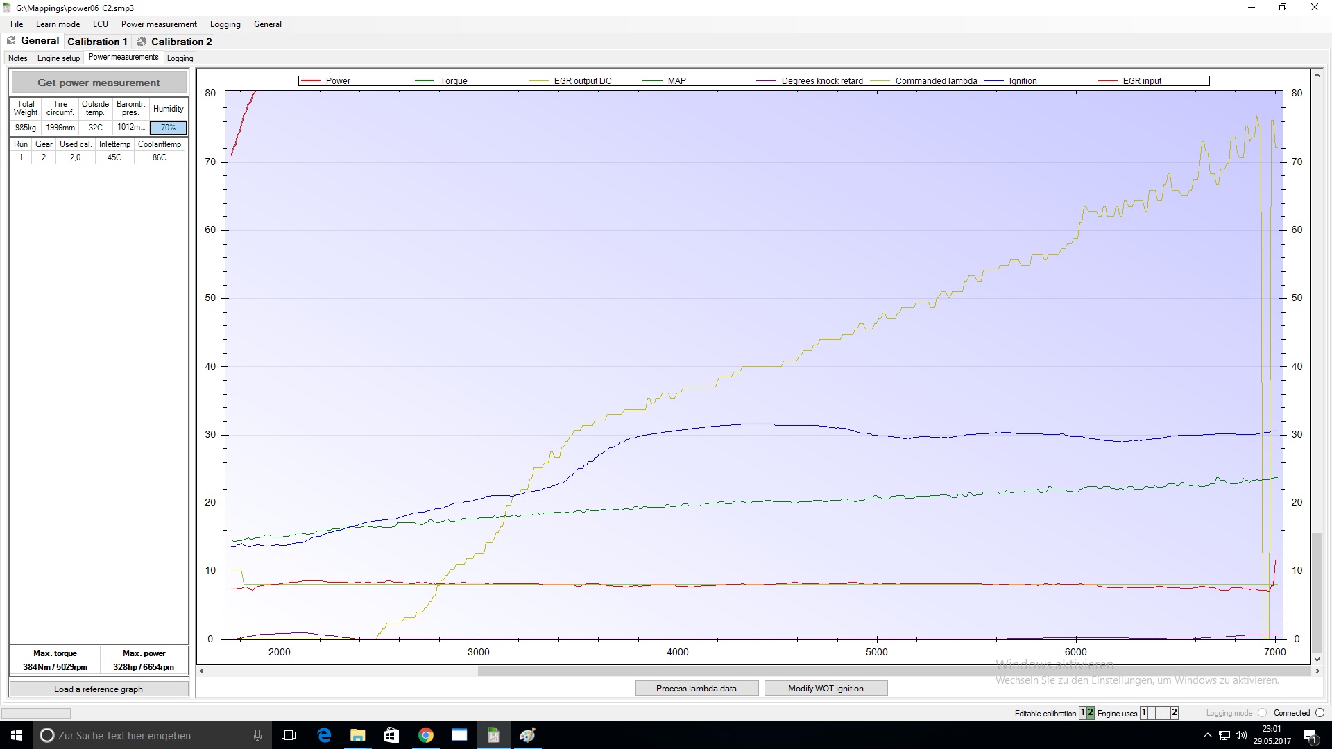
My boost is ~1,5 bar = 14,5 psi 

Pressure difference over the nozzle would be pressure of waterpump ( its always 150 psi) minus boost pressure -> 150 psi - 14,5 psi = 135,5 psi


Now you look into the table and search for the best nozzle that provides ~326 cc/min @ 135,5 psi 

As we want to have two nozzles in parallel, you must look for 326 cc/min / 2 = 163 cc/min @ 135,5 psi 


jetrate-nc-bg4.gif


In this case you would end up somewhere between the yellow and the green line, but closer to the yellow line. 

You must choose one of both. Do you wan tto have more or less water ? Lets calculate with both nozzles how the water / fuel ratio will be: 


Yellow Nozzle: 150 cc/min @ 135 psi (in total 300 cc/min)

Blue Nozzle : 200 cc/min @ 135 psi (in total 400 cc/min)


Devide that thorugh the max fuel flow and you get the ratio.

Our max fuel flow is 4x 680 cc/min = 2720 cc/min


Yellow Nozzle: 300 / 2720 = 0,110 -> 11% water

Blue Nozzle: 400 / 2720 = 0,147 -> 14,7% water


You must now choose one of these ;)

You can calculate it the same way with your own boost and fuel nozzle sizes. 


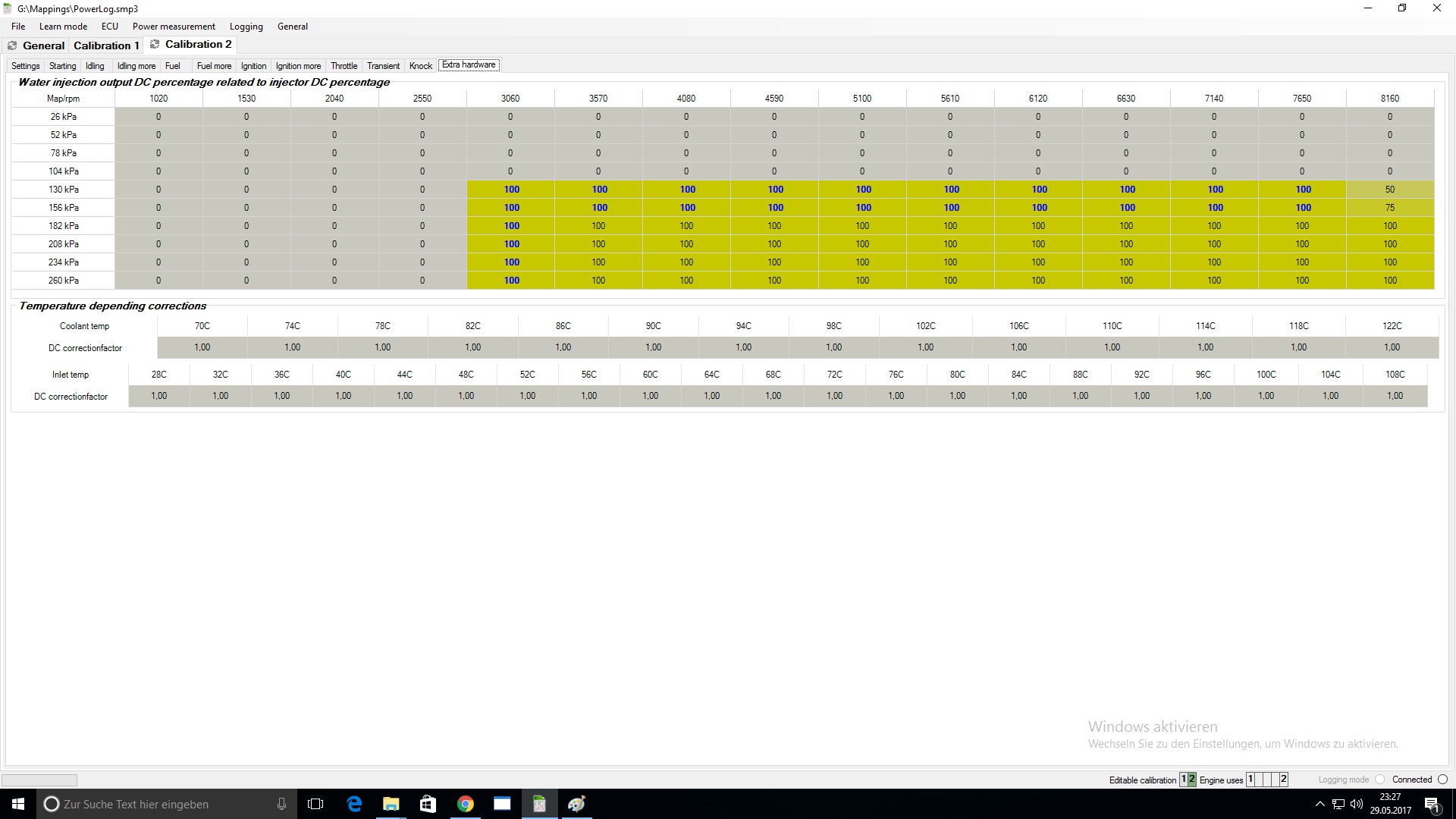
I would always take the bigger nozzle for future upgrade and if you use OBD Tuner pro you can minimize the water flow by multiplying the IDC. (watch at my link) 


More Infos for setting up the water IDC in OBD Tuner PRO can be found here (german) https://www.speedste...&comment=132201


Edited by FabianG, 09 December 2019 - 01:26 PM.


#6 FabianG

FabianG

    Member

  • Pip
  • 31 posts
  • Location:Germany

Posted 09 December 2019 - 01:30 PM

https://www.youtube....eature=emb_logo


Edited by FabianG, 09 December 2019 - 01:32 PM.


#7 Exmantaa

Exmantaa

    Scary Internerd

  • PipPipPipPipPipPip
  • 3,982 posts
  • Gender:Male

Posted 09 December 2019 - 01:54 PM

Good info, but I assume you are a bit colorblind and mean the yellow and green 0.5mm nozzle. :happy:


I'm not sure if Aquamist mimics the duty cycle to the nozzle FAV valve frequency, otherwise you should consider the max IDC in your fuel injector flow calculations.


Edited by Exmantaa, 09 December 2019 - 01:54 PM.


#8 FabianG

FabianG

    Member

  • Pip
  • 31 posts
  • Location:Germany

Posted 09 December 2019 - 03:27 PM

Good info, but I assume you are a bit colorblind and mean the yellow and green 0.5mm nozzle. :happy:


I'm not sure if Aquamist mimics the duty cycle to the nozzle FAV valve frequency, otherwise you should consider the max IDC in your fuel injector flow calculations.


You're right ! Its green instead of blue :)


With OBD Tuner and the aux-Input of the Aquamist ECU you can tell the Aquamist the exact fuel IDC in every moment.

So if you have 50% fuel IDC, the FAV (Fast Acting Valve for water nozzle) will also do 50% DC at that moment. That makes sure you always have the right water / fuel ratio. And Thats why you calculate the nozzle with 100% fuel IDC. 

I think the Aquamist itself has the optin to take the IDC from one of the fuel injectors directly, but then you can't modify it as extensive as with OBD Tuner Pro.

The table looks like that: 


Power06.jpg.09f6278fc66a959e3448a5ce51a7


In this case the FAV gets 100% of the fuel IDC. 

You could also type in more or less than 100%, depending on your nozzle size and your desired amount of water. 

If you would type in 50% in all the cells, then the water nozzle would open just half the time of the fuel nozzle. Your water / fuel ratio will be the half.


With that Table you can also define very easy at what point of time the WAES is triggered and how "strong" 


Power02.jpg.78fdfae12a652756607010c915cd


The yellow line shows the "EGR Output DC". Thats the DC which is sent to the FAV. 

You must be sure that the ignition (blue line) is rising AFTER you are enjecting water (yellow line). 

As you can see, you are able to rise the ignition a lot. And thats where the extra power comes from.

With Methanol you can rise that ignition curve even more. But then you will need a bigger nozzle because the ideal fuel / water mixture is changing: 


  • 100% water:  10-15% water/fuel ratio or 0-5-1cc per BHP 
  • M50/W50: 15-20% MW/fuel ratio or  1-1.5cc per BHP
  • 100% methanol: 20-25% methanol/fuel ratio or 1.5-2cc per BHP 


I wrote that because a lot of people dont understand that its not just installing the System. If you want it to run correct and efficient, you have to put some work into it.  


I hope I was not color blind again :D


Edited by FabianG, 09 December 2019 - 03:35 PM.


#9 Firthy

Firthy

    Super Duper Member

  • PipPipPip
  • 576 posts
  • Gender:Male
  • Location:Surrey

Posted 09 December 2019 - 10:02 PM

Thank you, Fabien this is incredibly useful information, for a complete beginner which Iam….


My car is a standard Stage 2 so I don’t want more power I just want sustain power and make the engine healthier 😊

If you know the size of your fuel nozzles you have to multiply them by 4 and by the % you want to have water added. 


Bosch VXR Blue 470 CC  4 x 470 cc/min = 1880 cc/min 

I want to inject pure water so the mixture has to be 10-15%, lets say 12% -> 1880 x 0,12 = 225.6 cc/m 

Stage 2 boost is ~0.8 bar = 12 psi 

Pressure difference over the nozzle would be pressure of waterpump ( its always 150 psi) minus boost pressure -> 150 psi - 12 psi = 138 psi


Now you look into the table and search for the best nozzle that provides ~225.6 cc/min @ 138 psi 

As we want to have two nozzles in parallel, you must look for 225.6 cc/min / 2 = 112.8 cc/min @ 138 psi 


Divide that through the max fuel flow and you get the ratio.

Our max fuel flow is 4x 470 cc/min = 1880 cc/min


Light blue nozzle Nozzle: 105 cc/min @ 138 psi (in total 210 cc/min)


Light Blue Nozzle:  210/1880 = 0,110 -> 11% water


So I guess the 0.4mm B (M1.5) would be the option.


Regarding the tank setup I see a lot of people running the baffled 5 litre tank on the rear parcel shelf next to the pump which is what I had planned to do….

Do you need a second pump in this scenario?


As its stage 2 I’m hoping peter can send me a map and it can be as plug and play as possible.


Thanks for all the help


Elliot


Edited by Firthy, 09 December 2019 - 10:03 PM.


#10 Zoobeef

Zoobeef

    Joes bedroom assistant.

  • PipPipPipPipPipPipPip
  • 11,102 posts
  • Gender:Male
  • Location:Retford/Bovington

Posted 10 December 2019 - 09:58 AM

I have the smallest nozzles. As I wanted to add no more power just just inject enough to keep temps stable.

As I couldn't use it though the cars all set up for it but the pump and controller are removed. Once I stick them back in I'll do some proper testing to see what temps are like.


#11 Firthy

Firthy

    Super Duper Member

  • PipPipPip
  • 576 posts
  • Gender:Male
  • Location:Surrey

Posted 10 December 2019 - 11:08 AM

I have the smallest nozzles. As I wanted to add no more power just just inject enough to keep temps stable.
As I couldn't use it though the cars all set up for it but the pump and controller are removed. Once I stick them back in I'll do some proper testing to see what temps are like.

Thanks mate do you think the nozzles as calculated above will give my stage 2 car too much additional power?

Edited by Firthy, 10 December 2019 - 11:08 AM.


#12 FabianG

FabianG

    Member

  • Pip
  • 31 posts
  • Location:Germany

Posted 10 December 2019 - 11:56 AM

Your EGT and IAT will drop and you will gain a little more power because of the cooler combustion. A lot of the cooling happens inside the cylinder during the compression process because a lot of the water spray is evaporating inside the cylnder. 

That means, that your engine is running much healthier than before, because everything is cooler.

To get the full potential you have to modify the ignition table. If you dont want more power then dont touch it. 

BUT: The load on your engine will be the same, even if you dont touch the ignition. You burn the same amount of fuel and the released energy will be the same. The power just wont get transfered into rotation, but more into friction and heat. 

So in my opinion it makes no sense to leave the ignition as it was. It wont do any damage but why waste power that is produced anyway ? 


Another BUT: If you madify the ignition to gain more power, you really should configurate the fail-safe. The Aquamist is controlling the water flow, the FAV and the water level. 

If one of these values doesnt match the ones that you configurated, it will send a fail-safe signal with inverted logic. Peter uses one Port of the ECU (I think it was the EGR) to detect that fail safe switch. 

You have the option to switch between maps with this port if there is something worng with your water System. Thats very important because if you modified the ignition to an agressive level and your water system fails, you can damage your engine. 

But with the fail-safe it is no Problem. 


I have one mapping for max power, agressive Ignition, running 15% pure water and 102 Octane fuel. 

And another safe mapping for less power, less ignition, no water, 98 Octane fuel. 


If the Aquamist detects something wrong, it will send the fail safe and my ECU automaticly switches to my second safe mapping. 

Also if I am somewhere where I cant get any 102 Octane fuel, I can press the button to switch off the Aquamist. That will switch to the safe mapping too because of the inverted logic (0V="1" 5V="0")


If thats too much work for you then Im sure you can just ask Peter for a mapping that works fine with water. 

But If you have OBD Tuner Pro, why dont use all the functions you have ? 


Also: Dont use my ignition curve for your setup. It will be different on each engine, depending on what hardware you are using ! 


Edited by FabianG, 10 December 2019 - 11:58 AM.


#13 Zoobeef

Zoobeef

    Joes bedroom assistant.

  • PipPipPipPipPipPipPip
  • 11,102 posts
  • Gender:Male
  • Location:Retford/Bovington

Posted 10 December 2019 - 12:25 PM

That was my main reason for not adjusting tables. If I run out of water the car would just run like it always has. I only have the standard software.


#14 Firthy

Firthy

    Super Duper Member

  • PipPipPip
  • 576 posts
  • Gender:Male
  • Location:Surrey

Posted 10 December 2019 - 01:08 PM

Thank Fabian that's brilliant I was planning to use OBD Tuner Pro to have full control plus fail safe if needed.

The only reason Zoobeef and I would not touch the ignition is because it's a standard engine and we don't want it to produce too much extra power and snap a rod.

If adjusting the ignition won't snap a rod I'm all in :)

Are my calculations correct and if so do you agree with the nozzle choice?

And do you need the lifter pump if you use the aquamist baffled 5 litre tank on the parcel shelf?

Edited by Firthy, 10 December 2019 - 01:14 PM.


#15 FabianG

FabianG

    Member

  • Pip
  • 31 posts
  • Location:Germany

Posted 11 December 2019 - 12:15 PM

Your calculations are correct and I would also choose that nozzle for your setup. 

I dont know how your configuration looks like when its installed. 

The intake of the high pressure pump has to sit on the same level (or lower) as the exit of your water tank. 


So just make sure your pump isnt sitting above your tank. Every amount of water that sits below your pump wont be sucked in by the high pressure pump ! 


Picture took from the Aquamist user manual.

Attached File  aquamist.JPG   22.98KB   3 downloads


The reason why I chose an extra pump was that I have a big 10 liter universal water tank. 

Because it is that big, the pump wouldnt get the water when driving through fast long corners on the race track. The water will swap to the other side of the tank.

So I installed a very samll (0,5 liter) catchtank that is always filled up by the additionial pump. The High pressure pump sits below that catchtank and is always safe to get enough water. 


58259c3e79ed9_WhatsAppImage2016-10-12at1


(The canister was just for testing ;) )


#16 Firthy

Firthy

    Super Duper Member

  • PipPipPip
  • 576 posts
  • Gender:Male
  • Location:Surrey

Posted 11 December 2019 - 01:30 PM

Thank you so much for your help Fabian its all becoming clear now :)


My last hurdle to jump is the electrics as I'm totally useless with wiring.


I know everything is accessible from the loom of doom area but I have no idea how to actually do it.


Elliot


#17 FabianG

FabianG

    Member

  • Pip
  • 31 posts
  • Location:Germany

Posted 11 December 2019 - 01:38 PM

I think its difficult to help you there. 

I would say, just try it or get someone who knows how to do it or who can help you. 

Its all wirtten in the Aquamist and OBD Tuner Manuals. Read them carefully and try your best ;) 


#18 Firthy

Firthy

    Super Duper Member

  • PipPipPip
  • 576 posts
  • Gender:Male
  • Location:Surrey

Posted 11 December 2019 - 10:35 PM

One more quick question but does everyone use this method to splice into the loom?


It makes it look quite easy if I have the tool and know which ones I need to cut :)


https://www.youtube....h?v=cWkLgkqMVfY


Edited by Firthy, 11 December 2019 - 10:39 PM.


#19 aquilaproejct

aquilaproejct

    Super Member

  • PipPip
  • 267 posts
  • Location:Australia

Posted 12 December 2019 - 10:08 AM

I normally cut twist and solder, which I am pretty confident with.

These are for if you are not confident (duraseal)

https://au.rs-online...minals/0533673/

#20 Firthy

Firthy

    Super Duper Member

  • PipPipPip
  • 576 posts
  • Gender:Male
  • Location:Surrey

Posted 14 December 2019 - 11:19 PM

Regarding the 12v 15A switched feed can anyone point me in the direction of the best place to take this from and specifically which wire?

I believe it can be taken from the stereo or the wires in the loom of doom any specific guidance here would be very much appreciated!


0 user(s) are reading this topic

0 members, 0 guests, 0 anonymous users