Jump to content


Photo

T Maps Sensor Wiring


  • Please log in to reply
24 replies to this topic

#1 JimmyJamJerusalem

JimmyJamJerusalem

    So annoying I got my own room.

  • PipPipPipPipPipPipPip
  • 10,382 posts
  • Gender:Male
  • Location:South Wales, God's country!
  • Interests:Music, Cars, Beer, Boxing.

Posted 12 June 2013 - 03:00 PM

I'm currently doing a Harrop/Dutch ECU conversion on a customers car and the postman has just dropped a T Map sensor off at my house (0281002437).  I wasn;t expecting it, but guess I am to fit it....


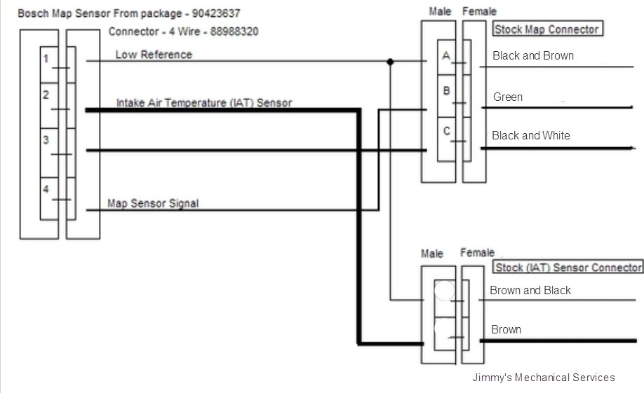
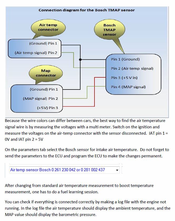
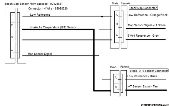
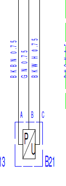
Plug doesn't match the current MAP sensor plug so I guess there's some rewiring to do....  Does anybody have details on what I'm looking for at this point as I've not had chance to look?


Cheers,


#2 techieboy

techieboy

    Supercharger of Doom

  • 22,914 posts
  • Gender:Male
  • Location:Bedford

Posted 12 June 2013 - 03:02 PM

Instructions are in the manual for the OBDTuner software.

#3 techieboy

techieboy

    Supercharger of Doom

  • 22,914 posts
  • Gender:Male
  • Location:Bedford

Posted 12 June 2013 - 03:04 PM

Posted Image


#4 Mike (Cliffie)

Mike (Cliffie)

    Back in a VX

  • PipPipPipPipPipPipPipPip
  • 13,352 posts
  • Gender:Male
  • Location:North Yorkshire
  • Interests:Weaving weasels woolly hats.

Posted 12 June 2013 - 03:08 PM

You will need a new plug Jim, let me know where you find a new one, I posted earlier looking for a source.


#5 NickB787

NickB787

    Gone but not forgotten

  • PipPipPipPipPipPipPip
  • 7,813 posts
  • Gender:Male
  • Location:Bedford

Posted 12 June 2013 - 03:09 PM

I found an old Lambda plug which fits but I will need it.


#6 techieboy

techieboy

    Supercharger of Doom

  • 22,914 posts
  • Gender:Male
  • Location:Bedford

Posted 12 June 2013 - 03:12 PM

I've got 4 weird rectangular plugs on my Saab loom that look to be compatible. But, they might be too big given the limited space under the Harrop.


#7 NickB787

NickB787

    Gone but not forgotten

  • PipPipPipPipPipPipPip
  • 7,813 posts
  • Gender:Male
  • Location:Bedford

Posted 12 June 2013 - 03:14 PM

I will fit as I had it on the z20let setup (just) can't lock it down though the Harrop holds it in place.


Edited by NickB777, 12 June 2013 - 03:15 PM.


#8 techieboy

techieboy

    Supercharger of Doom

  • 22,914 posts
  • Gender:Male
  • Location:Bedford

Posted 12 June 2013 - 03:15 PM

This is the proper version


#9 JimmyJamJerusalem

JimmyJamJerusalem

    So annoying I got my own room.

  • PipPipPipPipPipPipPip
  • 10,382 posts
  • Gender:Male
  • Location:South Wales, God's country!
  • Interests:Music, Cars, Beer, Boxing.

Posted 12 June 2013 - 03:49 PM

Cheers for the info guys. 


I think this is the correct plug.  Just waiting to hear back from the seller to confirm


LINK


#10 techieboy

techieboy

    Supercharger of Doom

  • 22,914 posts
  • Gender:Male
  • Location:Bedford

Posted 12 June 2013 - 03:58 PM

Looks about right. There seems to be plenty of different compatible versions out there, depending on the car manufacturers preferred supplier.


#11 JimmyJamJerusalem

JimmyJamJerusalem

    So annoying I got my own room.

  • PipPipPipPipPipPipPip
  • 10,382 posts
  • Gender:Male
  • Location:South Wales, God's country!
  • Interests:Music, Cars, Beer, Boxing.

Posted 16 June 2013 - 10:39 AM

Hmmm, does anybody have any more information about wiring the TMAP sensor in....?


Looking at this pic I can't make any sense of it


Posted Image


Current MAP sensor connections are


A,  Black and brown

B,  Green

C,  Black and White


Posted Image

Not sure how to connect up stock connections into the New TMAP plug....?


#12 leevx2.2

leevx2.2

    Turbo's are for girls and throttle bodies are too slow

  • PipPipPipPipPipPip
  • 4,830 posts
  • Gender:Male
  • Location:Bedford
  • Interests:Taking apart vx220s for fun
    getting p!!sed
    genraly playing with large power tools

Posted 16 June 2013 - 12:11 PM

Cut the wires from the old stock conector if you look at t map sensor you will see the numbers 1 to 4 and conect wires to this as drawing black and brown to number 1 Black and white to number 3 Lt green to number 4 And then the same to the intake sensor plug Black in to number 1 splice it into wire Tan into number 2 job done

Edited by leevx2.2, 16 June 2013 - 12:13 PM.


#13 JimmyJamJerusalem

JimmyJamJerusalem

    So annoying I got my own room.

  • PipPipPipPipPipPipPip
  • 10,382 posts
  • Gender:Male
  • Location:South Wales, God's country!
  • Interests:Music, Cars, Beer, Boxing.

Posted 20 June 2013 - 04:40 PM

Last thing I promise.....


The IAT sensor connections are not


    [*] - Black
    [*] - Brown
    [/list]

    As stated above and in the drawings


    They're 


      [*] - Brown with black stripe
      [*] - Brown
      [/list]

      Is it fair to assume the brown with black stripe is what you are referring to above?


#14 JimmyJamJerusalem

JimmyJamJerusalem

    So annoying I got my own room.

  • PipPipPipPipPipPipPip
  • 10,382 posts
  • Gender:Male
  • Location:South Wales, God's country!
  • Interests:Music, Cars, Beer, Boxing.

Posted 20 June 2013 - 04:48 PM

Personally I think it may be the opposite...  Brown is used as a 'low referance' a few times in the circuit......?


IAT sensor


Posted Image


#15 Exmantaa

Exmantaa

    Scary Internerd

  • PipPipPipPipPipPip
  • 3,982 posts
  • Gender:Male

Posted 20 June 2013 - 05:18 PM

Easy to check, as the 2 low references are probably connected together inside the ecu...


#16 JimmyJamJerusalem

JimmyJamJerusalem

    So annoying I got my own room.

  • PipPipPipPipPipPipPip
  • 10,382 posts
  • Gender:Male
  • Location:South Wales, God's country!
  • Interests:Music, Cars, Beer, Boxing.

Posted 20 June 2013 - 08:51 PM

Oooh, sneaky sneaky, good thinking Frank, I'll bell it out and check it that way.


So looking at the A4  (the ecu), do you think there will be continuity across terminals 38, 39 and 22....?


Also would you think that would mean that these terminals are the low reference connector as that contradicts the bottom drawing.....  has anyone actually done this yet?


Posted Image


Posted Image


#17 Exmantaa

Exmantaa

    Scary Internerd

  • PipPipPipPipPipPip
  • 3,982 posts
  • Gender:Male

Posted 20 June 2013 - 10:53 PM

I don't know the internal ecu pin layout, but just measure if 2 (low refrence) wires (map + iat) are connected to ground...


#18 JimmyJamJerusalem

JimmyJamJerusalem

    So annoying I got my own room.

  • PipPipPipPipPipPipPip
  • 10,382 posts
  • Gender:Male
  • Location:South Wales, God's country!
  • Interests:Music, Cars, Beer, Boxing.

Posted 21 June 2013 - 09:23 PM

Right it was the other way around, brown is the low reference connection
 
I'm pretty sure this is right :)  even got some shameless advertising :lol:


Posted Image


#19 NickB787

NickB787

    Gone but not forgotten

  • PipPipPipPipPipPipPip
  • 7,813 posts
  • Gender:Male
  • Location:Bedford

Posted 26 June 2013 - 12:02 PM

great just about to do this and I have


green+black

purple + black


ahhh


Edited by NickB777, 26 June 2013 - 12:03 PM.


#20 techieboy

techieboy

    Supercharger of Doom

  • 22,914 posts
  • Gender:Male
  • Location:Bedford

Posted 26 June 2013 - 12:06 PM

I think, as Peter says in his manual, the key is to forget about wire colours and do it all based on the positions of the pins in the connectors.


Posted Image


0 user(s) are reading this topic

0 members, 0 guests, 0 anonymous users