Jump to content


Photo

Project Pig Stage 3/4 Build

stage 4 project p16vxx

  • Please log in to reply
58 replies to this topic

#1 Andy_VX

Andy_VX

    Scary Internerd

  • PipPipPipPipPipPip
  • 2,050 posts
  • Gender:Male
  • Location:Bournemouth
  • Interests:Cars, Boats, F1, Cycling, Home Cinema, Music.

Posted 25 January 2017 - 07:20 PM

[color=#1a1a1a;][font="arial;"]Hi guys, [/color][/font]


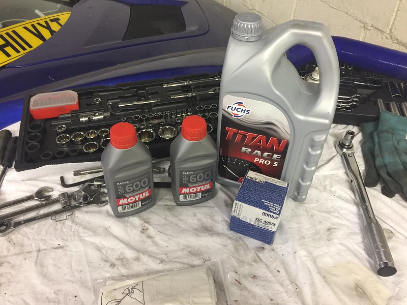
[color=#1a1a1a;][font="arial;"]Thought I’d start a project thread for my VXT stage 4 build I’m doing over the next couple of months. This is more for my benefit more than anything else, as I’d like to have a record of all the work done, nothing new that hasn't been done before. I've sourced the majority of the used parts from Alex who has been really helpful with answering all of my questions![/color][/font]


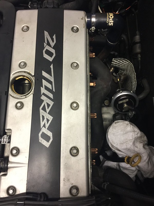
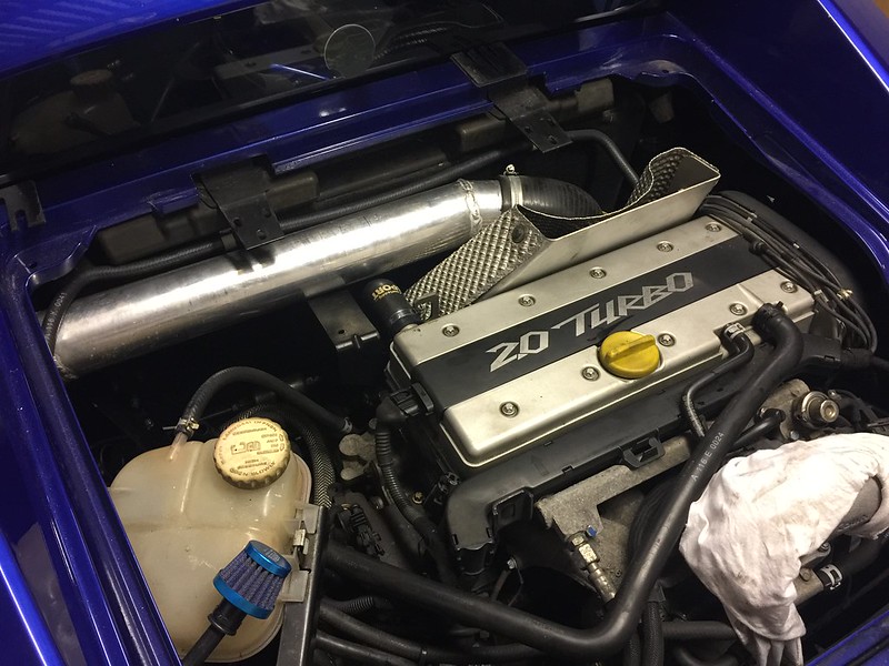
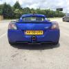
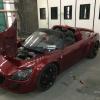
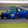
[color=#1a1a1a;][font="arial;"]Bit of history about the car, it's a 2003 coral blue turbo. My Dad bought it as cat C registered car back in 2005, we rebuilt the car together and I subsequently purchased it from him in 2011 (21st) It was a 1 owner car that had been tuned by Courtenay a few months prior to it being crashed! I guess this was in the really early days before the Pro Alloy CC kit was around as it had a "Pace" charge cooler fitted, although the cooler and pre-rad look good enough the hoses used were not up to the job at 10mm! I had the car on a RR a few years ago and it produced about 250BHP, must admit I was a bit surprised at the figure as it doesn't feel crazy quick like cars of a similar tune do. Seems to be reliable enough on the road but when you're pushing hard on track, Snetterton 300 especially you can see the IAT rise and the ECU backs everything off. [/color][/font]


[color=#1a1a1a;][font="arial;"]I've spent quite a bit of time getting the handling right so when the parts I wanted came up for grabs 2nd hand I decided to bite the bullet and upgrade the power and reliability to make what will hopefully be my perfect car! [/color][/font]


[color=#1a1a1a;][font="arial;"]Parts to be changed include:[/color][/font]


[color=#1a1a1a;][font="arial;"]Pro Alloy Charge Cooler[/color][/font]

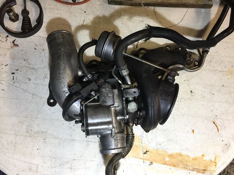
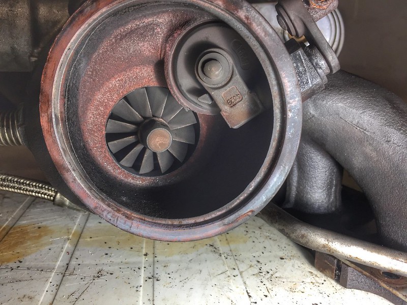
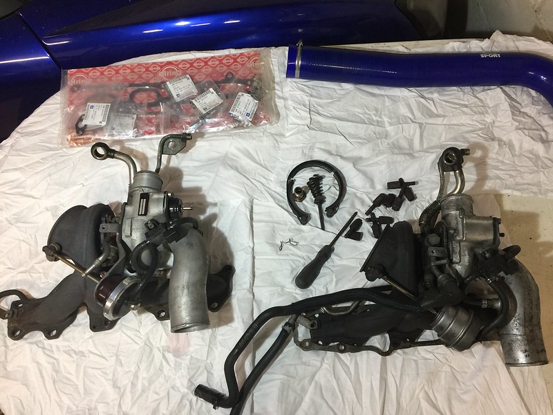
[color=#1a1a1a;][font="arial;"]K06 Turbo (new gaskets / studs etc.)[/color][/font]

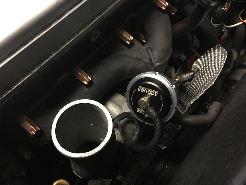
[color=#1a1a1a;][font="arial;"]Turbosmart Actuator [/color][/font]

[color=#1a1a1a;][font="arial;"]Turbosmart Re-circ Valve[/color][/font]

[color=#1e1e1e;][font="helvetica;"]Deka 630cc injectors[/color][/font]

[color=#1a1a1a;][font="arial;"]80mm AFM[/color][/font]

[color=#1e1e1e;][font="helvetica;"]80mm intake pipe [/color][/font]

[color=#1e1e1e;][font="helvetica;"]Air filter (may modify the [/color][/font]air box)


[color=#1e1e1e;][font="helvetica;"]Going to do the work myself over a few weekends, really enjoying it so far, it's nice to do a job without having to rush for once! I will replace / refurbish any worn bits along the way (though most things are up together now). [/color][/font]


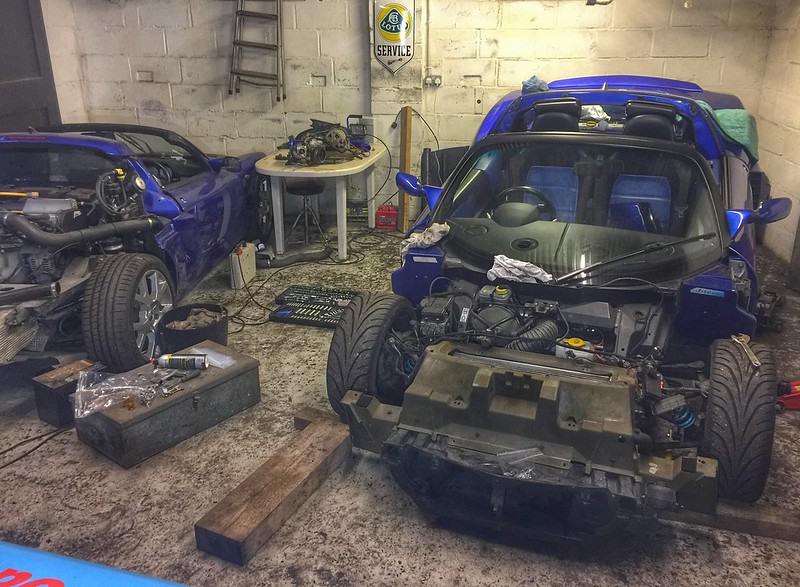
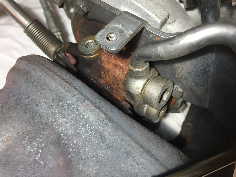
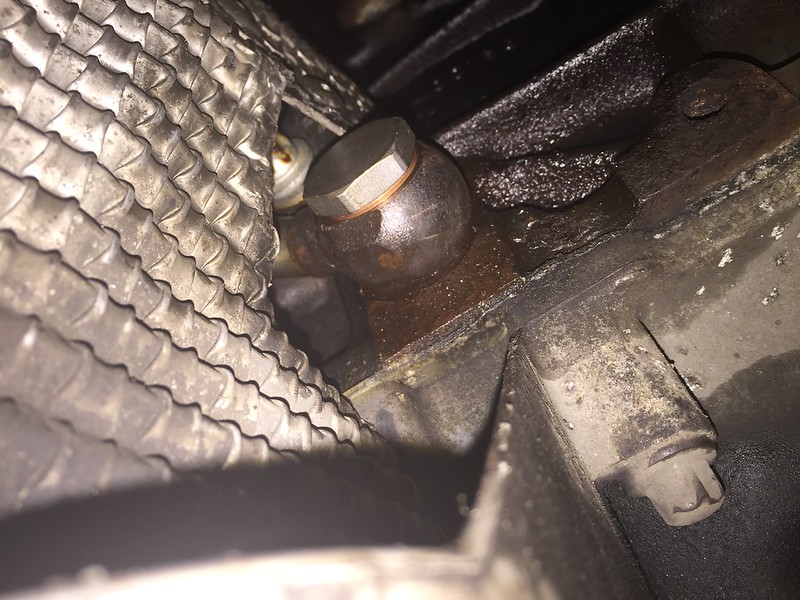
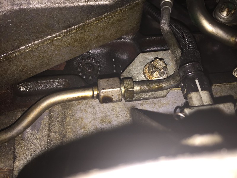
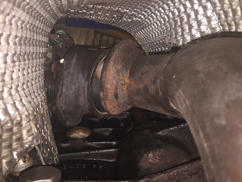
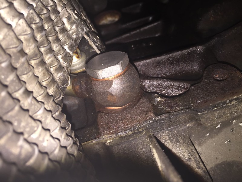
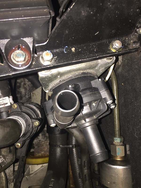
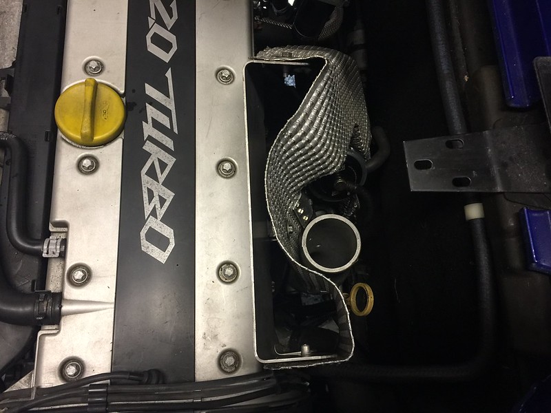
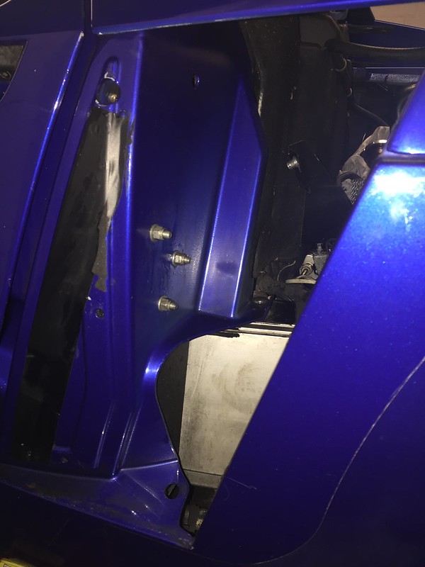
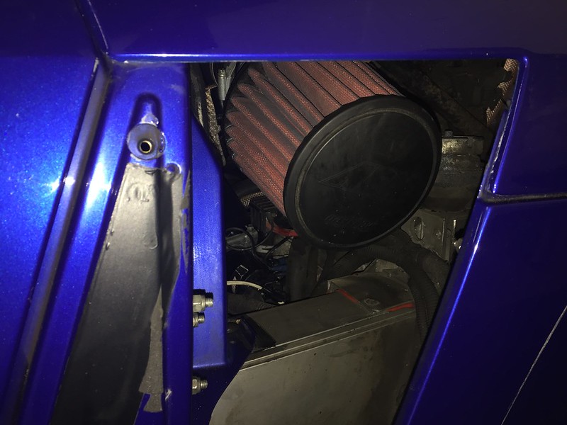
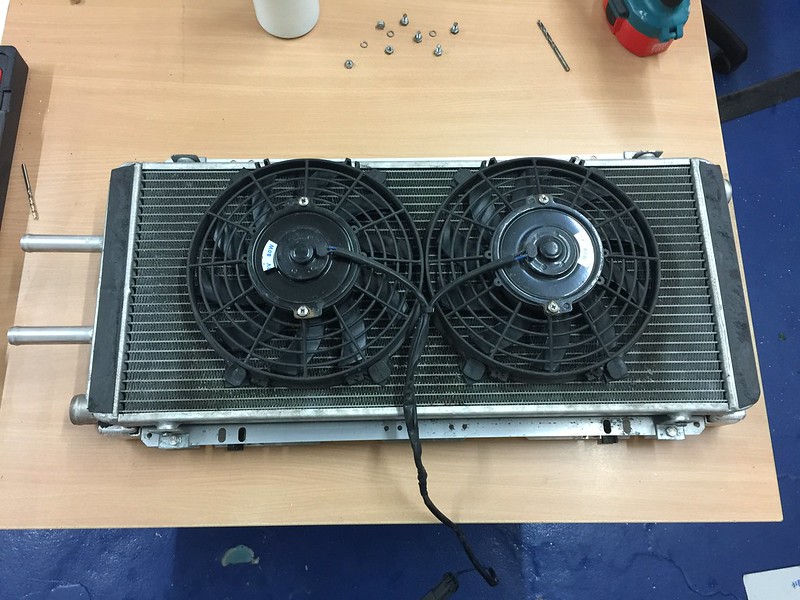
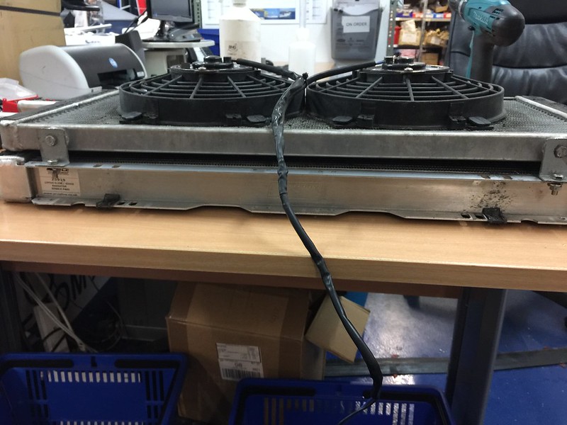
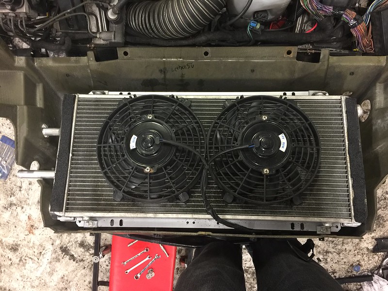
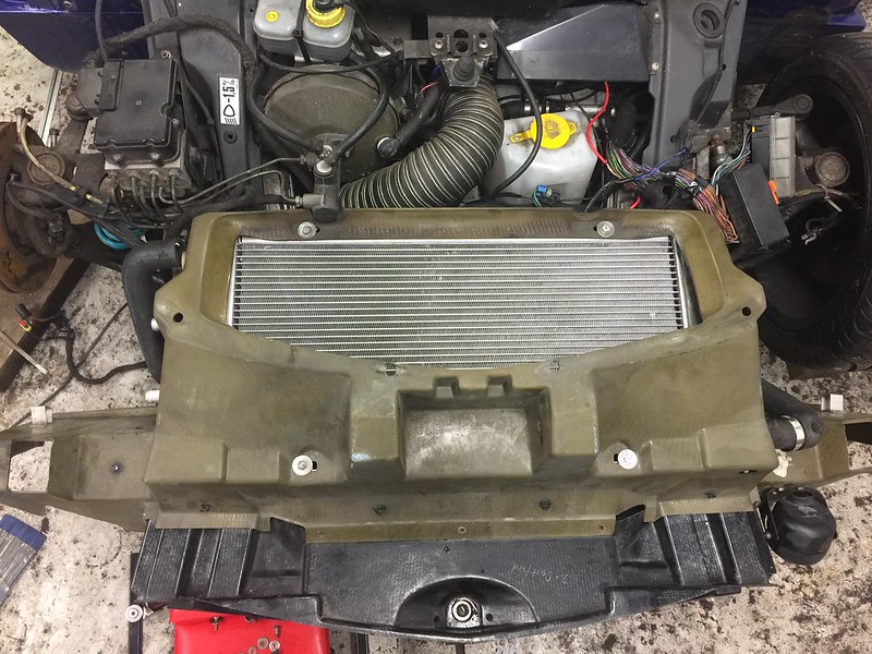
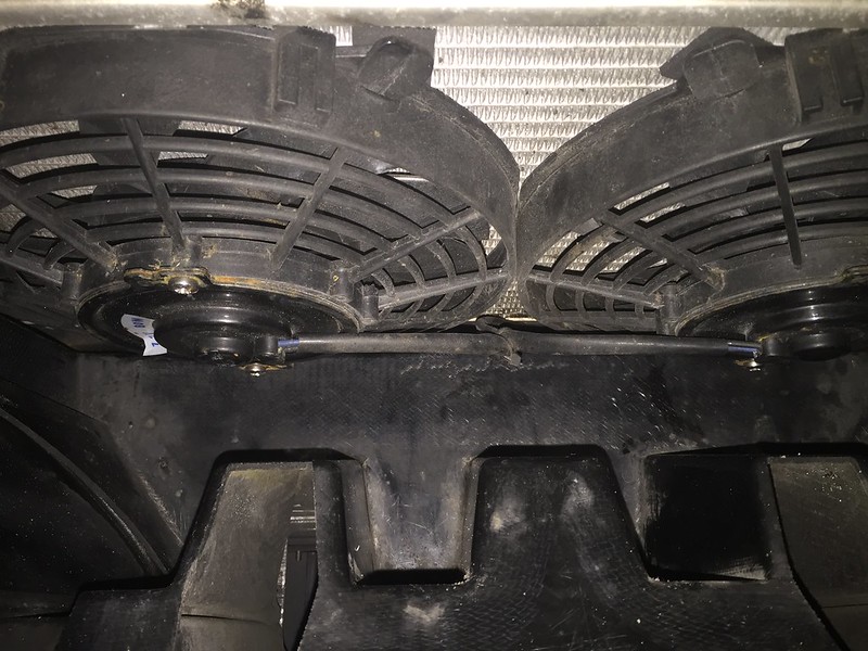
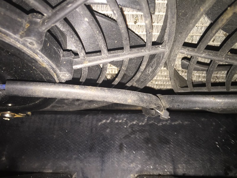
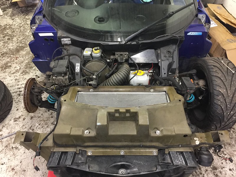
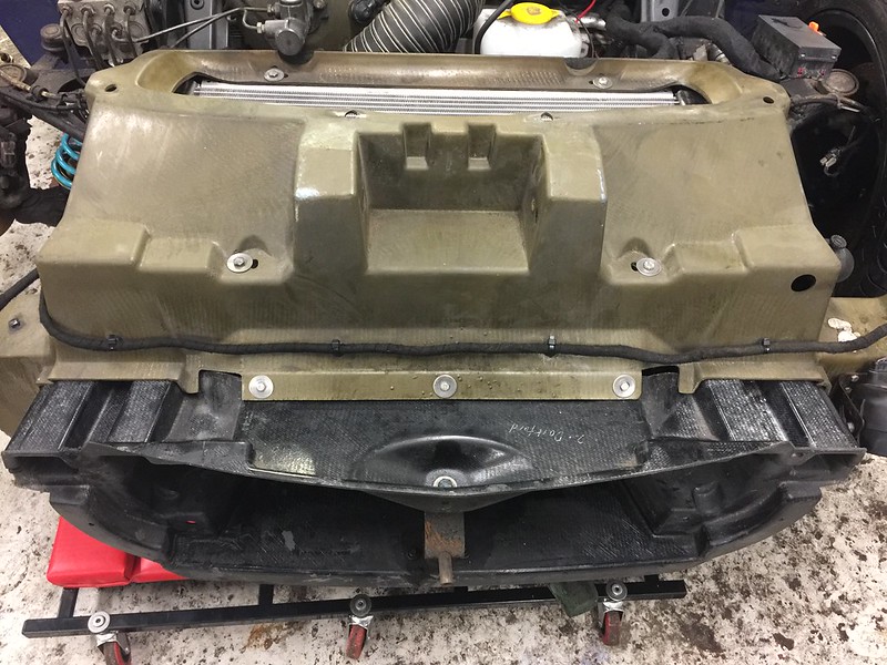
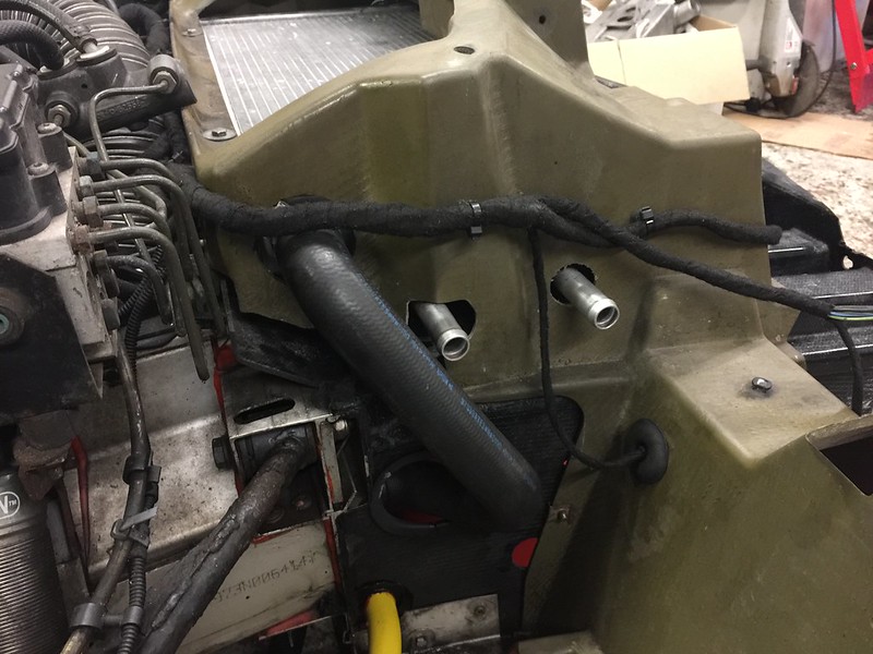
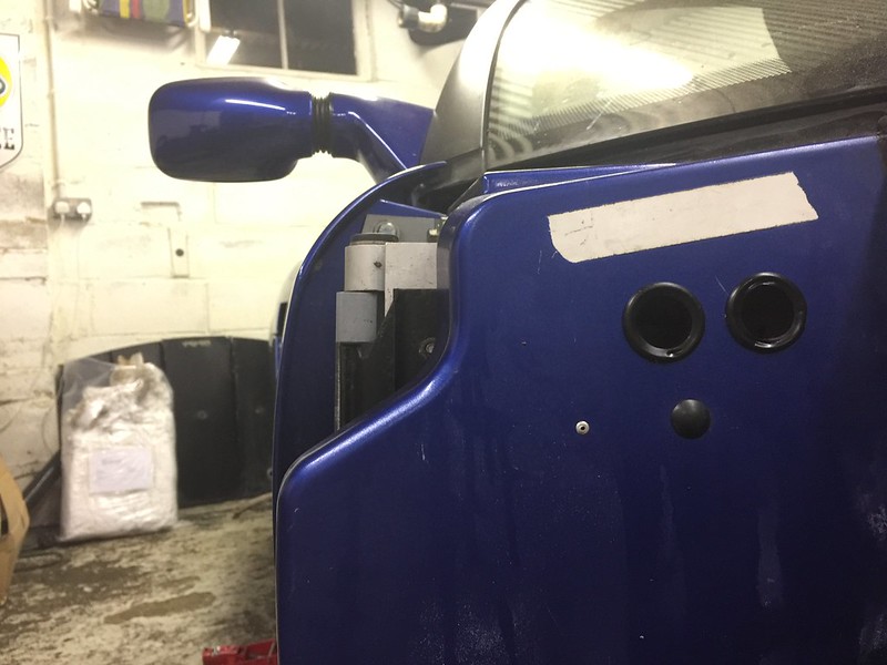
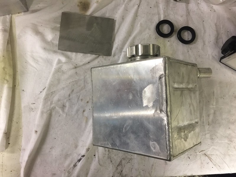
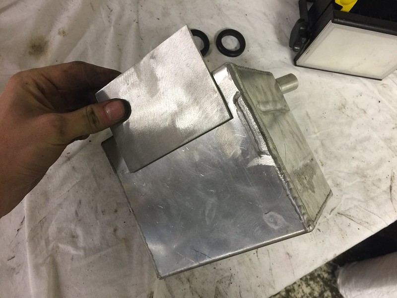
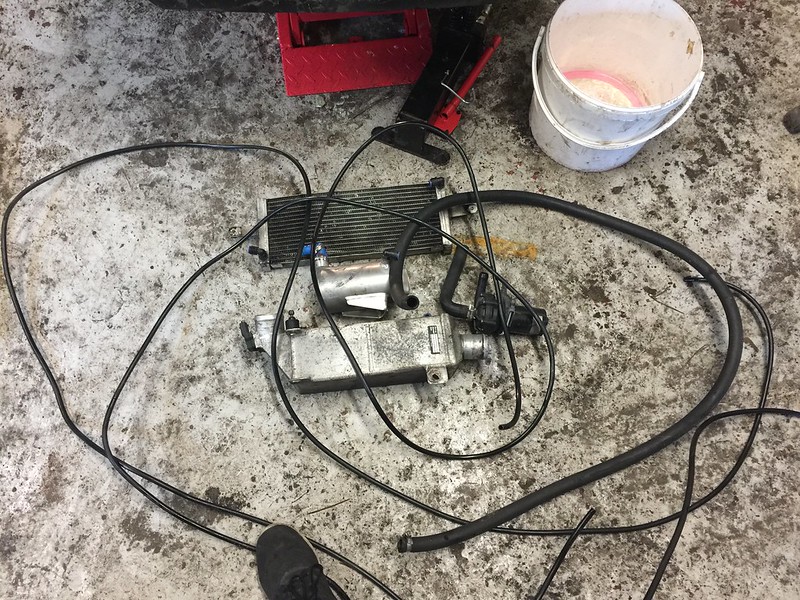
[color=#1a1a1a;][font="arial;"]Spent last Saturday taking the front clam off and removing the old Pace charge cooler system, the pre-rad sat directly in front of the grille with the hoses running through the cockpit via the centre console alongside the gear cables. The heat exchanger looks to be a bit smaller than the pro-alloy version and so was easy enough to remove without taking the rear clam off. Then there's the reservoir that I always thought was in a stupid place right next to the hot engine! I think the main issue with the kit is just the lack of volume. It's probably possible to weld some new connectors onto the hardware and run 19mm hoses throughout which would help but I'd rather do it properly! [/color][/font]


Posted Image


Posted Image


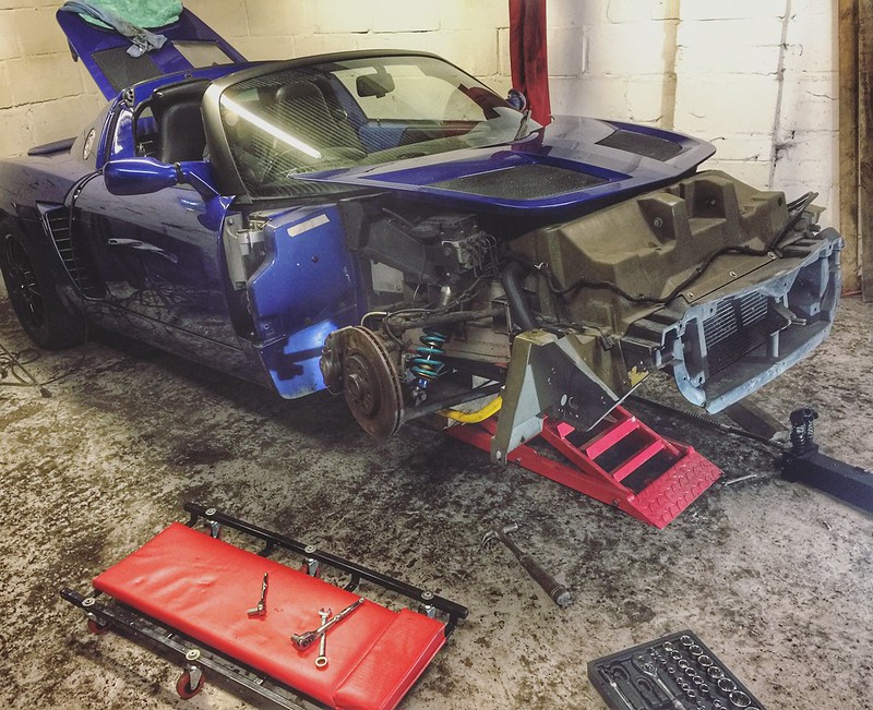
Not got the new parts yet but I'll probably get the rear clam off on Sunday just to make access easier! No doubt i'll be asking lots of silly questions along the way, but I really can't wait for it to be done! :)


#2 Andy_VX

Andy_VX

    Scary Internerd

  • PipPipPipPipPipPip
  • 2,050 posts
  • Gender:Male
  • Location:Bournemouth
  • Interests:Cars, Boats, F1, Cycling, Home Cinema, Music.

Posted 04 February 2017 - 07:06 PM

Made a bit more progress today, half the battle was getting the car in the air with faulty ramps but I got there in the end after fun and games with 3 jacks!

Today I removed the all of the associated pipework for the turbo / charge cooler and drained the coolant. Then removed the coolant and oil feeds to the turbo. Managed to get the turbo out easily enough so pretty much ready to install the new parts that are due to arrive next week.

My suspicions about the turbo were right, seemed to be a little bit of play in the turbine so I think swapping it out for the K06 was a good choice. Looks in very good condition overall though, manifold looks mint and the gasket showed no sign of pitting. The old turbo should be good as new after a service. (See my for sale thread £150).

Next week I'll get the Pro Alloy charge cooler and turbo installed.

Posted Image


Posted Image


Posted Image


Posted Image


Posted Image


Edited by Andy_VX, 04 February 2017 - 07:09 PM.


#3 tibby

tibby

    Super Duper Member

  • PipPipPip
  • 504 posts
  • Gender:Male
  • Location:Belgium
  • Interests:POWER

Posted 06 February 2017 - 10:53 AM

Nice one.... Glad to see another turbo build :tt: :tt: 


#4 Andy_VX

Andy_VX

    Scary Internerd

  • PipPipPipPipPipPip
  • 2,050 posts
  • Gender:Male
  • Location:Bournemouth
  • Interests:Cars, Boats, F1, Cycling, Home Cinema, Music.

Posted 09 February 2017 - 11:20 PM

The stage 4 parts arrived this week so I made a start and got the new turbo in. 


Posted Image


First job was to clean the face of the block and manifold ready for the new gasket, used some petrol on a clean rag whilst being careful not to get any muck in the engine. I bought the LET turbo fitting kit from Autovaux which includes studs, nuts, manifold gasket and all of the washers etc. 8 out of the 10 studs came out with the nuts so I replaced those and reused the other 2. 


Posted Image


Next job was to swap the coolant line over as the K06 came with a different pipe, presumably for the Astra configuration. I undid the oil restricting banjo bolt  and blanking plug and went to fit the coolant pipe to the new turbo, Unfortunately it wasn't as simple as i'd hoped as the small bracket that holds the pipe in place (1st photo) seemed to foul on the casing which meant I couldn't get the thread to catch. Managed to bend it upwards with some pliers which did the job. 


Posted Image


Posted Image


Once that was done I fitted the plate that goes between the manifold and nuts, offered the turbo up to the manifold and caught all of the nuts on, I'll torque them up properly tomorrow. I connected the main banjo bolt to the sump but couldn't remember if there were 2 copper washers i.e. one on the bolt and one on the sump side, can someone clarify that? The oil return line is just a simple nut to connect. 


Posted Image


Posted Image


So it's in, as ever it took a bit longer than I expected but it's done so I can start making some progress with the charge cooler. Unfortunately the heat shield has now seen better days but managed to bend it back into shape! 


Posted Image


Only thing I didn't manage was to connect the turbo to the down pipe, struggled to get it mated and do the v band clamp up at the same time, think it's a 2 man job really! I'm hoping tomorrow i'll be able to support it with a jack from underneath and then get the V band connected. 


Posted Image


Edited by Andy_VX, 09 February 2017 - 11:22 PM.


#5 Nev

Nev

    Nipper's Minion

  • PipPipPipPipPipPipPipPip
  • 11,587 posts
  • Gender:Male
  • Location:Bristol
  • Interests:Rock climbing, skiing, kayaking, surfing, mountaineering, budgies, chess, practical mechanics.

Posted 10 February 2017 - 07:12 AM

Yes, your banjo connection should have a copper compression washer on each side of it. Obviously clean them well, as any grit etc can cause a mild leak (and hence fire risk).


Edited by Nev, 10 February 2017 - 07:12 AM.


#6 siztenboots

siztenboots

    RaceMode

  • 26,610 posts
  • Gender:Not Telling
  • Location:Surrey
  • Interests:french maids

Posted 10 February 2017 - 07:29 AM

Yes, your banjo connection should have a copper compression washer on each side of it. Obviously clean them well, as any grit etc can cause a mild leak (and hence fire risk).  

Was going to say exactly same.

#7 Andy_VX

Andy_VX

    Scary Internerd

  • PipPipPipPipPipPip
  • 2,050 posts
  • Gender:Male
  • Location:Bournemouth
  • Interests:Cars, Boats, F1, Cycling, Home Cinema, Music.

Posted 10 February 2017 - 10:18 PM

More progress. 


First job was to fix yesterdays error, banjo washers sorted! 


Posted Image


Finally found a decent well priced precision torque wrench so torqued up the manifold nuts to 16nm.


Posted Image


Fancy over priced oil for the new turbo! 


Posted Image


Mounted the charge cooler pump whilst i still had access to that part of the bay, all wired up with a relay to run for a few minutes after ignition is turned off. 


Posted Image


Heat shield back on, it was split so I made up a reinforcing plate with some aluminium and bolted it in place which should stop it buzzing. 


Posted Image


80mm AFM and Intake Pipe installed with the new filter. 


Posted Image


Removed the airbox and bit of plastic that routes the air into the box. Not entirely happy with it atm as I don't think the air will be routed directly to the filter, rather just around the engine bay so need to find some sort of duct. 


Posted Image


Posted Image


Edited by Andy_VX, 10 February 2017 - 10:21 PM.


#8 Andy_VX

Andy_VX

    Scary Internerd

  • PipPipPipPipPipPip
  • 2,050 posts
  • Gender:Male
  • Location:Bournemouth
  • Interests:Cars, Boats, F1, Cycling, Home Cinema, Music.

Posted 11 February 2017 - 08:01 PM

Got the engine rad out and mounted the pre rad today. The foam has had it anyone know where to source it from? 


Posted Image


Posted Image


Edited by Andy_VX, 11 February 2017 - 08:03 PM.


#9 Arno

Arno

    Need to get Out More

  • PipPipPipPip
  • 1,233 posts
  • Gender:Male
  • Location:Netherlands

Posted 13 February 2017 - 08:18 AM

Make sure you fill the space between the rad and pre-rad along the edges with something like EDPM (or possibly neoprene) foam to stop air leaking out between them or taking a shortcut and bypassing the pre-rad. Air will try to take the easiest path if you don't and reduce the effectiveness.


Also use some nylon washers between the brackets and the rad(s) to provide some amount of thermal insulation and cut down on heat transfer/conduction from the cooling system radiator to the chargecooler rad.


Bye, Arno.


#10 Andy_VX

Andy_VX

    Scary Internerd

  • PipPipPipPipPipPip
  • 2,050 posts
  • Gender:Male
  • Location:Bournemouth
  • Interests:Cars, Boats, F1, Cycling, Home Cinema, Music.

Posted 13 February 2017 - 08:47 AM

Hi Arno,


Spent ages peeling it off the bottom of the engine rad as I thought it would make it too high! Guess I should've just cut it in half length ways. I need to get some more foam for the pre-rad to sit on anyway.


Cheers.


#11 thomasn

thomasn

    Member

  • Pip
  • 28 posts
  • Location:FRANCE

Posted 15 February 2017 - 08:28 AM

Hi,


what relay did you choose to switch on the pump after a few minutes ?

I need to do the same on mine, and i did not find a timed relay cheaper than £50  :huh:


#12 Andy_VX

Andy_VX

    Scary Internerd

  • PipPipPipPipPipPip
  • 2,050 posts
  • Gender:Male
  • Location:Bournemouth
  • Interests:Cars, Boats, F1, Cycling, Home Cinema, Music.

Posted 16 February 2017 - 11:27 AM

Did a bit more on the car last night, drilled the holes in the sill ready for the hoses. Also cut holes in the rad housing and got the rad mounted, I went to fit the housing back on the car only to find the pre-rad fans are fouling on the crash box, they sit too far back which obviously means i can't get the 3 bolts in the back of the housing screwed into the crash box. Has anyone else experienced this? 


Looks as if the only option is to make up some new brackets to secure the pre-rad further forward on the engine radiator, don't want to do this as i've drilled the holes in the housing now which will be in the wrong place if i have to move it!


Other option is to see if i can find slimmer fans. 


See photos below. 


Posted Image


Posted Image


Posted Image


Posted Image


Any advice appreciated! 


#13 SteveA

SteveA

    .

  • PipPipPipPipPipPipPip
  • 9,151 posts
  • Gender:Male
  • Location:North East UK

Posted 16 February 2017 - 12:02 PM

Any reason you have gone for two fans?


#14 mbes2

mbes2

    Someone say Plasti Dip?

  • PipPipPipPipPipPipPip
  • 8,508 posts
  • Gender:Male
  • Location:Feering, Essex
  • Interests:"Keep it standard"
    "Yes, I built it"

Posted 16 February 2017 - 12:08 PM

I remember the day I fitted my PA CC, start to finish around 8 hours, much tea was drank that weekend  chinky chinky

Always more fun doing it yourself for sure.


I think I went the one fan route for better air flow, even on the hottest of days, the CC tank never got that hot, such a great upgrade.


#15 Andy_VX

Andy_VX

    Scary Internerd

  • PipPipPipPipPipPip
  • 2,050 posts
  • Gender:Male
  • Location:Bournemouth
  • Interests:Cars, Boats, F1, Cycling, Home Cinema, Music.

Posted 19 February 2017 - 06:54 PM

Hi guys, CC rad came with 2 fans fitted so i've just left it, there's still plenty of air flow and will help when you're pushing hard on track etc. I got the pre-rad to sit down in the crash box properly now so no need to modify anything. 


Did a few odd jobs today and tided up a few niggles. 


Rads properly mounted and housing secured. I also wrapped the fuse box loom with some tape and cable tied the front loom back down, all fixings are stainless.


Posted Image


Posted Image


Holes cut in the housing and sill for the pre-rad hoses. 


Posted Image


Posted Image


I realised that the CC header tank is actually designed for the NA engine bay which mounts to the coolant tank instead of the boot lid support bracket. I cut the original bracket off and fabricated a new bracket that I will get my mate to weld up this week. 


Posted Image


Posted Image


Edited by Andy_VX, 19 February 2017 - 06:58 PM.


#16 SteveA

SteveA

    .

  • PipPipPipPipPipPipPip
  • 9,151 posts
  • Gender:Male
  • Location:North East UK

Posted 19 February 2017 - 07:05 PM

Hi guys, CC rad came with 2 fans fitted so i've just left it, there's still plenty of air flow and will help when you're pushing hard on track etc.

I think you will find exactly the opposite is true. The fans restrict air flow and only turn on when you are static. A lot of race cars remove radiator fans altogether as they are only any use when you are sitting in traffic.

#17 Andy_VX

Andy_VX

    Scary Internerd

  • PipPipPipPipPipPip
  • 2,050 posts
  • Gender:Male
  • Location:Bournemouth
  • Interests:Cars, Boats, F1, Cycling, Home Cinema, Music.

Posted 19 February 2017 - 07:38 PM

Yes I know that, for me I wanted everything to run cool even when im static hence the decision to go CC instead of IC. It's important to keep temps under control when you're inbetween sessions or checking pressures and the double fans will help with that. Pro alloy have run this setup so there's obviously sufficient air flow.

#18 Nev

Nev

    Nipper's Minion

  • PipPipPipPipPipPipPipPip
  • 11,587 posts
  • Gender:Male
  • Location:Bristol
  • Interests:Rock climbing, skiing, kayaking, surfing, mountaineering, budgies, chess, practical mechanics.

Posted 21 February 2017 - 06:31 PM

Yes I know that, for me I wanted everything to run cool even when im static hence the decision to go CC instead of IC. It's important to keep temps under control when you're inbetween sessions or checking pressures and the double fans will help with that. Pro alloy have run this setup so there's obviously sufficient air flow.


Impressive work.


You can add a simple toggle switch to the loom by the gearstick which will manually activate the 2 fans to stay on constantly. This helps a lot with temps (when either stationary or when blasting). If it is hot ambient and I am caning the car I switch them on and I never get coolant temps > 100 degrees. So overall the 2 fan system is great in my experience.  


Edited by Nev, 21 February 2017 - 06:33 PM.


#19 Andy_VX

Andy_VX

    Scary Internerd

  • PipPipPipPipPipPip
  • 2,050 posts
  • Gender:Male
  • Location:Bournemouth
  • Interests:Cars, Boats, F1, Cycling, Home Cinema, Music.

Posted 22 February 2017 - 09:20 AM

Thanks Nev, Yeah that's a good point I will get that sorted, been meaning to install the ABS cut off switch too. 


#20 Andy_VX

Andy_VX

    Scary Internerd

  • PipPipPipPipPipPip
  • 2,050 posts
  • Gender:Male
  • Location:Bournemouth
  • Interests:Cars, Boats, F1, Cycling, Home Cinema, Music.

Posted 22 February 2017 - 09:50 AM

Plan on getting the header tank and CC fitted this weekend, can someone just confirm this is the correct routing as my Dad had a look and seems to think otherwise. 


[color=rgb(40,40,40);font-family:helvetica, arial, sans-serif;]Bottom hose from header tank - Pump Inlet[/color]
[color=rgb(40,40,40);font-family:helvetica, arial, sans-serif;]Pump outlet - pre-rad inlet[/color]
[color=rgb(40,40,40);font-family:helvetica, arial, sans-serif;]Pre-rad outlet - CC water inlet (top front)[/color]
[color=rgb(40,40,40);font-family:helvetica, arial, sans-serif;]CC outlet - return to top of header tank.[/color]


[color=rgb(40,40,40);font-family:helvetica, arial, sans-serif;]Also, does it matter which is the inlet / outlet on the rad?[/color]


Edited by Andy_VX, 22 February 2017 - 09:52 AM.


Also tagged with one or more of these keywords: stage 4, project, p16vxx

0 user(s) are reading this topic

0 members, 0 guests, 0 anonymous users