Jump to content


Photo

Z22Se - Inlet Port Moulds (Pre-Reshaping)


  • Please log in to reply
15 replies to this topic

#1 blackoctagon

blackoctagon

    Member

  • Pip
  • 212 posts
  • Gender:Male
  • Location:Lothian

Posted 18 May 2021 - 02:31 PM

I'm about to make a new head for my new engine. I did make a reprofiled head for my car a number of years ago, and made a 2nd one around a year ago that never got fitted, but both times I only cleaned the port walls, knife endged the bifrucations and smoothed out the short-side and long-side radisuses (SSR and LSR, respectively). Just good-practise stuff.

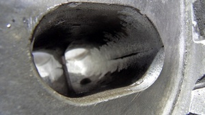
For the new head I decided to use port moulds to help me get a better look inside - all the angles and LED torches in the world cannot see right around the SSR I find.
This is how you get a mould of your ports.

CLICK PICTURES FOR BIGGER

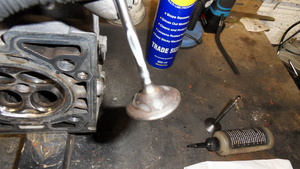
This is a good, tough, resilient RTV that i've used for years. It really holds together (as you'll see later).
MEAJIL_t.JPG

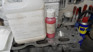
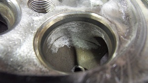
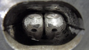
You'll need the valves to hold the RTV in, so coat them with a release agent so the RTV dosn't stick. Here I used a PTFE based bike chain lubricant, as I was in a bind once and tried it and it worked really well, so i've kept doing it.
MEAJIM_t.JPG


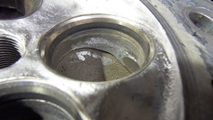
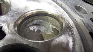
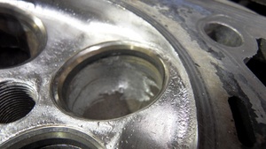
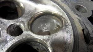
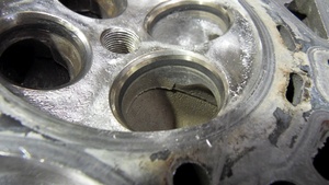
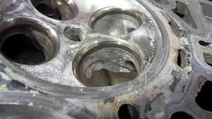
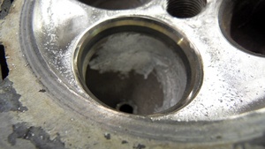
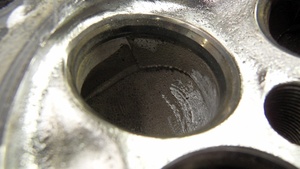
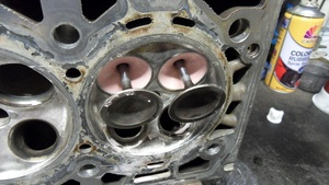
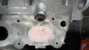
Coat the port walls as well:
MEAJKM_t.JPG


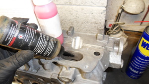
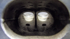
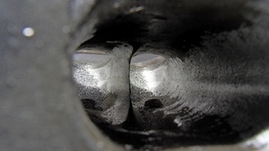
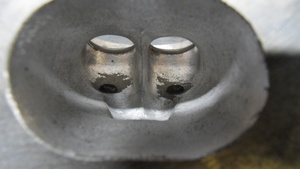
Here I taped the valves up, although normally i just refit the springs and locks:
MEAJLE_t.JPG

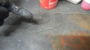
Get some wire and bend some 3D shapes into it. We'll embed it in the rubber while it cures so that it helps us pull the rubber out. The green Lego trees are great for this job if, like me, you don't mind upsetting children:
MEAJLF_t.JPG

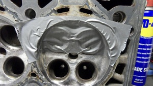
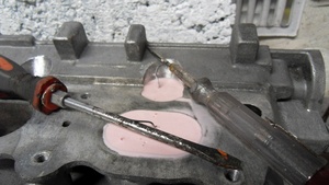
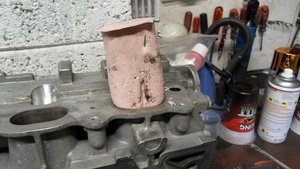
Mix your base and catalyst. Air will escape well enough in the port.
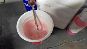
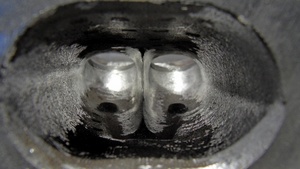
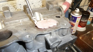
MEAJLG_t.JPG

Pour:
MEAJLH_t.JPG

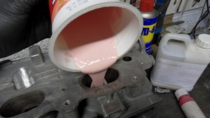
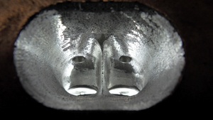
Half fill and leave for a few minutes, agitating with a stick/screwdriver to get air to rise out.
MEAJLI_t.JPG

Same again - pause for air:
MEAJLK_t.JPG


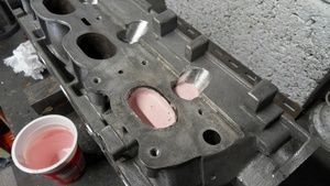
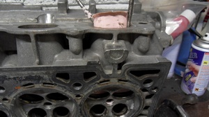
After 45 minutes pop in the wires:
MEAJLQ_t.JPG


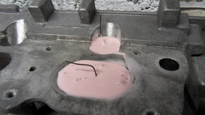
Hook them so they dont fall right in:
MEAJLS_t.JPG


I give it 24hrs. It probably takes 12.
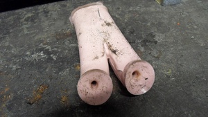
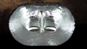
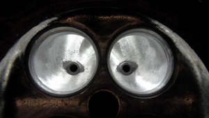
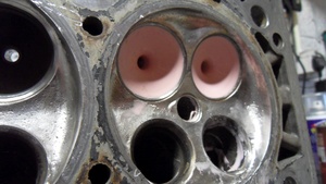
Now pop the valves.
MEAJLW_t.JPG


The valve stem holes in the rubber are important - this gives it a bit of 'give' when you are compressing the rubber to get it out. Some people mould a filled port, but I always leave the valves in to get that space. It makes a difference.
MEAJMA_t.JPG

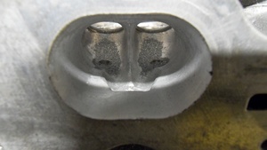
For these z22se ports you'll have to rip out the injector 'plug'.
MEAJMB_t.JPG

MEAJMC_t.JPG

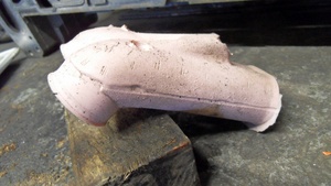
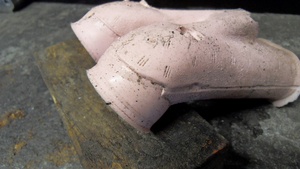
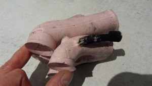
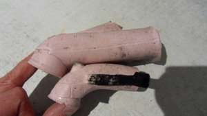
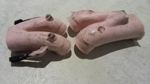
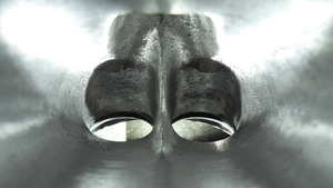
Using blunt screwdrivers start to wiggle the rubber out:
MEAJMD_t.JPG

Lever it side to side, but also go in to the combustion chamber side and and puch from the valve side, making sure to ease the rubber over the valve guide's protrusion.
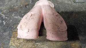
MEAJME_t.JPG

Keep working it
MEAJP3_t.JPG

MEAJP5_t.JPG


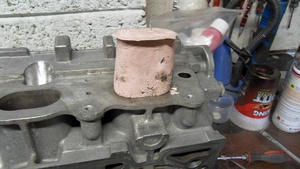
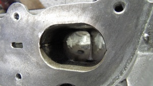
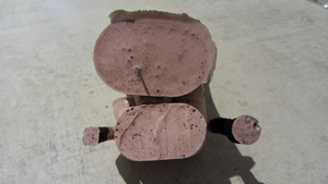
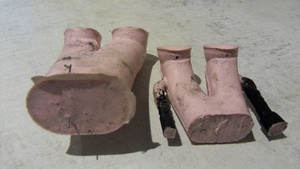
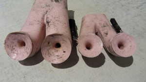
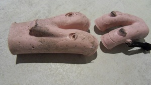
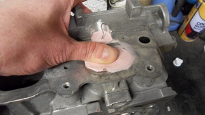
And there is a port mould (with most of the injector spray area)
MEAJP7_t.JPG

Edited by blackoctagon, 18 May 2021 - 02:35 PM.


#2 blackoctagon

blackoctagon

    Member

  • Pip
  • 212 posts
  • Gender:Male
  • Location:Lothian

Posted 18 May 2021 - 02:32 PM

I'll let you look at the mould and see for yourself the casting marks, the core shift and the general lack of precision present on the SSR and LSR before the valve. You can infer from it that the air flow would be sub-optimal, but if you've not see a port pull before I can assure you that this is normal in production engines.

MEAJPA_t.JPG

MEAJPC_t.JPG

MEAJQ4_t.JPG

MEAJQ5_t.JPG


When people like Honda made a big deal about the ports in cars like the old DC2 Integra Type R and some sports bikes they were often starting with a base casting like this. The re-shaping still took a bit of work even with optimised tooling and a pattern to work from, and that was on the factory clock.

When i've cut metal i'll re-mould the ports for comparison.

#3 OneYet

OneYet

    Billy No Mates

  • PipPipPipPipPip
  • 1,354 posts
  • Gender:Male
  • Location:Huskvarna, Sweden

Posted 22 May 2021 - 09:39 PM

This is some serious work.

I am impressed.


#4 FLD

FLD

    WANNABE MY LOVER

  • PipPipPipPipPipPipPipPip
  • 13,717 posts
  • Gender:Male
  • Location:Near nantwich
  • Interests:Tugging my todger.

Posted 23 May 2021 - 08:02 AM

If you think the inlet is bad wait until you pull a core from the exhaust ports. They’re terrible!

#5 Exmantaa

Exmantaa

    Scary Internerd

  • PipPipPipPipPipPip
  • 3,982 posts
  • Gender:Male

Posted 23 May 2021 - 11:22 AM

If you think the inlet is bad wait until you pull a core from the exhaust ports. They’re terrible!


That was the first thought I had when reading the tiltle; start with the tiny exhaust on a Z22, as the intake is plenty big enough...

#6 blackoctagon

blackoctagon

    Member

  • Pip
  • 212 posts
  • Gender:Male
  • Location:Lothian

Posted 25 May 2021 - 09:31 PM

I'll do a separate post on the exhausts - I have the pull from one and it's an eye opener alright.

The inlets meanwhile have been given some TLC to get them to, what I expect, the designers had in mind, plus a knife edge on the bifrucation. They really don't need much work at all.

I'll put up port and post-shaping pull photos when I have the camera in from the garage.

#7 blackoctagon

blackoctagon

    Member

  • Pip
  • 212 posts
  • Gender:Male
  • Location:Lothian

Posted 06 June 2021 - 09:26 PM

The inlet ports form the combustion chamber
Excuse the unclean head surface and tool marks - this head is getting a big skim to raise the CR so i've elected not to properly prepare it as I would if there was no skim going to be done.

This shows a lot of casting flash on the outside of the port wall. This head seems to have more of a flash problem than a core-shift one.
A fast, clean-up pass with the cutter was made:
MEU0QJ_t.JPG

Using the cutter and focusing on the overhanging flash
MEU0QL_t.JPG

Starting to blend the bowl, and the thin horizontal line that has appeared along the long-side radius is the offset from a core shift:
MEU0QM_t.JPG

A little bit more cutting and the core shift line is still with us, but the side wall flash removal is going well:
MEU0QO_t.JPG


Moving to the inside wall and there is a nasty, sharp flash and core shift.
Clearly i've kept the camera angle the same, but the side you cannot see if worked the same way - i'm not repeating all the cut photos.
You can also see the flow would come around the SSR and shear off towards the valve centre because of this so there is probably a fair bit of flow loss.
MEU0QQ_t.JPG

Cutting back the flash:
MEU0QR_t.JPG

Blending the edges of the SSR and the bowl - core shift line visible again:
MEU0QS_t.JPG


Turning the camera to the inner wall of the first port you can see the shift has not left as dramatic an effect because the shift is in the 'right' direction for the bowl shape:
MEU0QT_t.JPG

And back to the outer wall of the second port, and you can see the shift will be harder to treat here:
MEU0QU_t.JPG

#8 blackoctagon

blackoctagon

    Member

  • Pip
  • 212 posts
  • Gender:Male
  • Location:Lothian

Posted 06 June 2021 - 09:48 PM

This is a view from the inlet side of the cuts made above:
MEU0QV_t.JPG

Now to the port inlets.
An untouched inlet. You can see the little casting core bars all over the port and the flash and shift near the valve seats.
MEU0R2_t.JPG


Back to the ports in the post above.
The walls where the mould join lines are vissible are cleander up with light cuts.
MEU0R3_t.JPG

It's tempeting to just beast in and cut until you have flat walls but the flash is the only enemy here. The wall shape back here is fine.
MEU0R4_t.JPG

Then work the cutter up towards the LSR, SSR and bowl, just taking cuts to clean the surface of texture:
MEU0R5_t.JPG

The bifrucation is the next target.
Working on the port's inner walls the bifrucation should be sharp and also be cut back a little to allow the blend to the floor and roof to be sharper
MEU0R6_t.JPG

Clean the floor and get the floor to bifruction blend sharp, but also lay a slight curve into the floor each side of the bifrucation
MEU0R8_t.JPG

Do the same trick to the roof to bifrucation blend
MEU0R9_t.JPG


Then I get a finer cutter in to improve the sufaces and also do a bit more detail work (there is still a finer cutter stage then sanding to come)
MEU0RA_t.JPG

You can see almost all of the metal is clean except the middle of the LSR and the area around the valve guides - this is where i use the small and gentle cutters and rely more on sanding
MEU0RB_t.JPG


In these photos i've shown a full set of first and second cuts on one inlet - no one wants to see four sets of the same thing for each cylinder.

However, you need to plan your cutting.
It is all to easy to cut metal, see it shiny, then look again the next day with a slightly different colour from light oxidation and re-cut only to find you've taken away too much material.

Thats why I write down my cuts and do them in batches - all the wall flash removals, all the bowl flash removals etc. rather than do one port fully and then move to the next port - you'll find it hard to get consistency across the whole head and then have to measure eveything up with bore guages and fix the other three to the biggest one.
Then you get ports bigger than you wanted because you can cut a bit off but you cant cut a bit back on.


I'll show the sanded ports next.

#9 cwhite2

cwhite2

    Member

  • Pip
  • 224 posts
  • Location:Bedworth (near Coventry)

Posted 11 June 2021 - 02:31 PM

Top work here mate I must say, you have way more patience and talent than me to be able to do that thumbsup 


#10 blackoctagon

blackoctagon

    Member

  • Pip
  • 212 posts
  • Gender:Male
  • Location:Lothian

Posted 18 June 2021 - 06:28 PM

Thanks, I certainly have patience.


Here is a standard inlet vs. a standard exhaust (click for bigger):

ME10F9A_t.JPG
Please notice the air pump ports are cast as well - the ports will create a reflective pressure wave in the exhaust and I am doing something about them.
If this was a steady-state flow, like a water pipe, the ports would just be dead ends and would fill up and not cause any problems in terms of drag or wave action
Because of the gas temperature as the valve opens and the high cylinder pressure released the overall effect is probably quite small, but I'm going to sort these ones on the grounds that; a. you would not design that flow feature in, b. GM did not put them in all Ecotec/L850 family engines, c. I can.

I believe, but will stand corrected. that the sand-cast head on the B207s and some US models do not have the air pump ports, so that's probably another good reason to use a sand-cast head for modifying.
ME10F9B_t.JPG

If you remember your old physics classes you'll know that hot gas is less dense then cool gas and easier to pump, and if you know your engine theory you'll know that fast exhaust gas is usually a good thing, so a smaller exhaust port than inlet is the norm. But this is eye-opening.

There are in/out ratios that you can find in textbooks/papers that will get your clean sheet design started, but doing a quick measurement leaves me scratching my head.
The z22se is fairly tractable low down (which I do like), and GM will have simulated and tested the living daylights out of the whole engine family. Plus, the product portfolio of the time (and upcoming vehicles the powertrain engineers would have known about from the development pipeline) was, as time has shown us, pretty bland worldwide, but the port just seems mean.

I'm of the opinion that they decided the turbo would take up the slack for vehicles that needed more power. There was probably also an emissions question that wasn't quite solved at the time, but the EGR sorted it immediately and VVT improved on later.
ME10F99_t.JPG

The next few shots are without comment:
ME10F98_t.JPG

ME10F96_t.JPG

ME10F8W_t.JPG

ME10F8V_t.JPG


The detailed exhaust shots will be in an Exhaust thread.

#11 Lightning002

Lightning002

    Newbie

  • 0 posts
  • Gender:Male
  • Location:Cambridge

Posted 13 July 2021 - 06:41 AM

Interesting stuff!


#12 Baron Von Scubadaddy

Baron Von Scubadaddy

    STAGE 3.333333333333333333333333333333

  • PipPipPipPipPipPipPip
  • 6,645 posts
  • Gender:Male
  • Location:North London
  • Interests:Girls, Cars,..... ! spending time asking questions about why my car won't work

Posted 13 July 2021 - 10:43 PM

Love your casting skills mate !

i do something similar but for different reasons.

Our heads are sh*t aren't they ????!!!!


#13 Baron Von Scubadaddy

Baron Von Scubadaddy

    STAGE 3.333333333333333333333333333333

  • PipPipPipPipPipPipPip
  • 6,645 posts
  • Gender:Male
  • Location:North London
  • Interests:Girls, Cars,..... ! spending time asking questions about why my car won't work

Posted 13 July 2021 - 10:45 PM

you could polish the whole thing and a make a cnc wonder head 


#14 cucharillas

cucharillas

    Member

  • Pip
  • 63 posts
  • Gender:Male
  • Location:zaragoza - Spain

Posted 15 July 2021 - 09:24 AM

interesting :popcorn:


#15 blackoctagon

blackoctagon

    Member

  • Pip
  • 212 posts
  • Gender:Male
  • Location:Lothian

Posted 04 August 2021 - 10:44 PM

I finally found time to begin polishing the ports up:

This is 120 grit from the head face to just before the start of the SSR.

The SSR, LSR and bowls have not had any sanding applied yet, but despite the terrible appearance due to harsh lighting the fine-cutting stage still gives a better finish that factory foam-cast when you run your finger over it.

ME2KSG5_t.JPG

#16 blackoctagon

blackoctagon

    Member

  • Pip
  • 212 posts
  • Gender:Male
  • Location:Lothian

Posted 22 August 2021 - 05:21 PM

240 grit in the bowls now and I shall not take the inlets further.
(Its not actually taking this long to do - i'm just bad at managing the photos uploads because I put everything in folders)
ME31IJX_t.JPG

The horrible looking edges where the injector relief meets the top of the port is, in reality, very smooth, but as anyone who has ever reshaped a post will know lighting is the difference between a glossy looking and rough looking port. The finger test is the arbiter, and these feel very smooth.

The little black marks however are lost-foam casting porosity, and I take it as a fact of life with these heads. I'm sure the sand cast LSJ/B207 give happier results.

The valve guides are all in tolerance and fine condition, so i'm not minded to fit news ones, but on the other hand I could taper and shape the noses on new ones so I am in a quandry.

The mould of the new port shape is next. That part is happening in real time to this thread.


5 user(s) are reading this topic

0 members, 1 guests, 0 anonymous users


    Bing (4)