Presuming the inlet manifold is not plastic, has anyone fiddled with their inlet to get some gains? My Clio got a suprising gain with this approach...around 8bhp and it only cost me £150.
If anyone has gone this far, has the ECU dealt with it OK?

Inlet Mods?
Started by
robfenn
, Apr 09 2007 12:27 AM
26 replies to this topic
#1

robfenn
-
-

- 1,955 posts
Billy No Mates
- Location:Kent
- Interests:Sports, Photography, Travelling, Racing Cars.
Posted 09 April 2007 - 12:27 AM
#2
Joe-Turbo
-
-
- 4,176 posts
Scary Internerd
- Gender:Male
- Location:Rayleigh, Essex.
Posted 09 April 2007 - 12:51 AM
hmm, i seem to remember an n/a owner having noz fitted but blew his plastic inlet manifold... could be wrong though
#3
luna_s
-

-
- 1,934 posts
Billy No Mates
- Gender:Male
- Location:North East Of England
Posted 09 April 2007 - 02:07 AM
i was toying with the idea of making an inlet for my N/A, but lost focus,
the plastic manifold is pretty good anyway
#4
speedster
-

-
- 3,600 posts
Future of Speed
- Gender:Male
- Location:Space
- Interests:Music Engines Birds Whiskey and Cosmology
Posted 09 April 2007 - 04:40 AM
You need to talk with vocky  He was perfected the standard inlet manifold!
He was perfected the standard inlet manifold!
Edited by speedster, 09 April 2007 - 04:42 AM.
#5
vocky
-

-

- 11,969 posts
Moderator
- Gender:Male
- Location:Earth
Posted 09 April 2007 - 02:48 PM
the standard 2.2 inlet is plastic and can be tweaked a little  I perhaps went a bit to far and cut my vx220 inlet open to port the inside too
  But basically you need to port match the manifold to the head and also open up the area below the throttle body.
I can't find the pics on here, so will post some later
But basically you need to port match the manifold to the head and also open up the area below the throttle body.
I can't find the pics on here, so will post some later 
I perhaps went a bit to far and cut my vx220 inlet open to port the inside too
But basically you need to port match the manifold to the head and also open up the area below the throttle body.
I can't find the pics on here, so will post some later
#6
vocky
-
-
- 11,969 posts
Moderator
- Gender:Male
- Location:Earth
Posted 09 April 2007 - 04:38 PM
this is the original thread where I found the idea to sort the standard inlet manifold...J-Body
here is the inlet manifold I cut open to port the inside, for some reason I never took a pic of the finished work

I have dotted the enlargement area, the black arrow is where to be careful.
I would recommend getting a spare manifold to work on, that's what I did

here is the inlet manifold I cut open to port the inside, for some reason I never took a pic of the finished work
I have dotted the enlargement area, the black arrow is where to be careful.
I would recommend getting a spare manifold to work on, that's what I did
Edited by vocky, 09 April 2007 - 04:34 PM.
#7
robfenn
-
-
- 1,955 posts
Billy No Mates
- Location:Kent
- Interests:Sports, Photography, Travelling, Racing Cars.
Posted 10 April 2007 - 02:47 PM
Thanks for your replies 
#8
mandarinvx
-

-
- 12,621 posts
King of First Replies
- Gender:Male
- Location:West Mids / Oxfordshire

#9
speedster
-
-
- 3,600 posts
Future of Speed
- Gender:Male
- Location:Space
- Interests:Music Engines Birds Whiskey and Cosmology
Posted 11 April 2007 - 02:58 PM
There's the GM performance one too - a tad pricey tho
That baby is a BIG-ish mani... Don't think it will fit in the limited space available

#10
luna_s
-
-
- 1,934 posts
Billy No Mates
- Gender:Male
- Location:North East Of England
Posted 11 April 2007 - 03:24 PM
I was thinking of a similar design just with curved runners, so it fits in the space, probably more hassle than its worth
#11
speedster
-
-
- 3,600 posts
Future of Speed
- Gender:Male
- Location:Space
- Interests:Music Engines Birds Whiskey and Cosmology
Posted 11 April 2007 - 03:45 PM
I was thinking of a similar design just with curved runners, so it fits in the space, probably more hassle than its worth
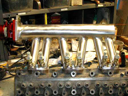
Checkout out my dbilas's angled runners HERE
#12
luna_s
-
-
- 1,934 posts
Billy No Mates
- Gender:Male
- Location:North East Of England
Posted 11 April 2007 - 04:56 PM
does the dbilas run without the ecu upgrade it comes with ?
the runners look quite short too ?
#13
MikeF
-
-
- 685 posts
Super Duper Member
- Location:Teesside
Posted 11 April 2007 - 04:57 PM
I was thinking of a similar design just with curved runners, so it fits in the space, probably more hassle than its worth
Checkout out my dbilas's angled runners HERE
the dbilas is sh*t, the runners are too short
im trying to help luna_s design on at the moment that he can make, iirc the correct runner length for the 2.2 should be around 25cm
I would appreciate some technical know how regarding this, I will post my calculation later once I have double checked them
Mike
p.s. heres some food for thought regarding runner length
Resonance tuning occurs in the following manner. During an intake valve opening, air is drawn into the engine at very high speed and therefore, has a good deal of momentum. When the intake valve shuts abruptly, the air in the runner continues to move down the runner, creating a high-pressure area on top of the intake valve. This high-pressure zone will travel up the runner until it comes into contact with the dense, slow moving air in the plenum. This collision causes a hard reflection and a high-pressure wave to travel back down the runner to the intake valve. If the runner is the correct length, the intake valve opening will coincide with the high-pressure wave’s arrival. This will force more air into the cylinder, allowing for volumetric efficiencies over 1.0 (Winterbone).
Edited by MikeF, 11 April 2007 - 04:59 PM.
#14
speedster
-
-
- 3,600 posts
Future of Speed
- Gender:Male
- Location:Space
- Interests:Music Engines Birds Whiskey and Cosmology
Posted 11 April 2007 - 05:54 PM
the dbilas is sh*t, the runners are too short
It not all about lenght you know! On my machine the dbilas intake is currently giving me great midrange and top end torque. The dbilas design considers runner lenght + runner width + plenum volume, meaning it takes full advantage of plenum induced high-pressure return waves. The TB mounting point is also calculated with air entry angles playing into the equation. Add to that the plenum + runner connection points.
If your going to design something yourself you'll need to at least calculate runner width as well as your runner lenght to insure you maintain good air speeds. And your longer runners will only work 100% successfully if you have air intake + plenum volumes big enough to produce good hard reflection down those extended runners, creating the high-pressure runner return waves that literally push the Air/Fuel charge into your NA engine.
Of course if your FI'd none of this really matters....
#15
MikeF
-
-
- 685 posts
Super Duper Member
- Location:Teesside
Posted 11 April 2007 - 06:15 PM
I would keep the runner circumference exaclty the same as the intake on the head, there is no reason to change this (or none that I can see)
as stated in my previous post, I believe runner length to be extremly important (as you state so is the volume, which is how i calculated my length of approx 25cm using the intake diameter)
now the plenum should get equal airflow to each runner, looking at the dbilas intake again I believe that the 4th runner gets significantly better airflow that the other 3 this i believe is due to the angled runners, something i dont believe works, and having scoured the internet is the only company I have seen who make use of angled runners like this
i would be interested to put the dbilas on a manometer/flow bench and look at the flow rates, I would also like to see some pics of it not installed in a car looking down the runners and through the hole where the throttle body attached
sorry is that all makes no sense, was typed quickly as im at work
forgot to say, the plenum size on the dbilas seems reaosnable, I would like to know its CC if you know it, the smaller plenum should give for a faster throttle response, does this ring true?
im designing plenum chambers now at work... lol
anyway here goes with what I think it should look like (nothing to scale of course, took me 30 seconds in paint)

and a cross section showing the throttle body

also ive been thinking about the runner lengths some more on the dbilas and something luna_s said to me, why does the dbilas have a seperate ECU? is it to do with the runner lengths?
as stated in my previous post, I believe runner length to be extremly important (as you state so is the volume, which is how i calculated my length of approx 25cm using the intake diameter)
now the plenum should get equal airflow to each runner, looking at the dbilas intake again I believe that the 4th runner gets significantly better airflow that the other 3 this i believe is due to the angled runners, something i dont believe works, and having scoured the internet is the only company I have seen who make use of angled runners like this
i would be interested to put the dbilas on a manometer/flow bench and look at the flow rates, I would also like to see some pics of it not installed in a car looking down the runners and through the hole where the throttle body attached
sorry is that all makes no sense, was typed quickly as im at work
forgot to say, the plenum size on the dbilas seems reaosnable, I would like to know its CC if you know it, the smaller plenum should give for a faster throttle response, does this ring true?
im designing plenum chambers now at work... lol
anyway here goes with what I think it should look like (nothing to scale of course, took me 30 seconds in paint)
and a cross section showing the throttle body
also ive been thinking about the runner lengths some more on the dbilas and something luna_s said to me, why does the dbilas have a seperate ECU? is it to do with the runner lengths?
Edited by MikeF, 11 April 2007 - 06:42 PM.
#16
speedster
-
-
- 3,600 posts
Future of Speed
- Gender:Male
- Location:Space
- Interests:Music Engines Birds Whiskey and Cosmology
Posted 11 April 2007 - 07:27 PM
also ive been thinking about the runner lengths some more on the dbilas and something luna_s said to me, why does the dbilas have a seperate ECU? is it to do with the runner lengths?
I thought dbilas provided a remap for the standard ECU. If they provide a standalone is probably to compensate for the massive change in fuel deliver you get if you run with the standard ECU fuel maps. If you use the ECU standard injector map, after 3800RPM, on WOT you'll run the injectors near max-cycle and end up with an AFR in the 11's!
Design looks good but do research the effect of all those sharp corners. Look at the dblias, no right angles, nice smooth round ends on the plenum and the runner and intake connections are rounded off. This helps provide more uniform air volumes to each of the cylinders. With corners you'll have turbulence and air bouncing around the manifold, meaning you can't manage air volume delivery down each of your runners, efficiently.
BTW Angled runners aren't uncommon
No idea on the dbilas plenum volume....... Maybe the folks at Regal might assist you.
Edited by speedster, 11 April 2007 - 07:42 PM.
#17
Winstar
-

-
- 4,264 posts
Scary Internerd
- Gender:Male
- Location:Chesterfield
Posted 12 April 2007 - 01:17 AM
I would keep the runner circumference exaclty the same as the intake on the head, there is no reason to change this (or none that I can see)
you should try to keep the runner the same cross sectional area and shape as the port any change will cause extra pressure loss.
as stated in my previous post, I believe runner length to be extremly important (as you state so is the volume, which is how i calculated my length of approx 25cm using the intake diameter)
Runner lengths are important to the performance the intake manifold, however the wave tuning effect of a manifold will only be effective at a narrow band of revs in a rev range, IIRC short runners will give good torque at mid to high rpm and long will give good torque lower down the rev range, hence why alot of modern engines employ a variable inlet manifold (VIM), this can be somthing simple as actuated flaps that allow the flow to travel through two different inlet tracts or like the Enzo engine that has telescopic trumpets that change the inlet length.
These lengths are determined by using 1d engine simulation software that calculates the affet of the wave reflection, (Clipping Point has used a free single cylinder version for his manifold), then once the lengths are determined in 1d the design is then analysed as a transient 3D simulation (which was my old job).
now the plenum should get equal airflow to each runner, looking at the dbilas intake again I believe that the 4th runner gets significantly better airflow that the other 3 this i believe is due to the angled runners, something i dont believe works, and having scoured the internet is the only company I have seen who make use of angled runners like this
Hmm, not sure why you think that?
I'd say looking at the design the 1st runner would get a lower mass flow that the others as the flow in the plenum will still be affected bt the throttel valve. Also the 4th runner may get a lower flow rate than the middle two as the plenum maintains the same cross section the gas velocity will be lower at the top of the runner.
As for the angled runners i ths application they would be better than square as when flow tuns a sharp corner it creates an aerodynamic 'pinch' or restricrtion thus reducing the effective volume of the runners, a way around this is to trumpet the end of the runner so that the flow can come round the corner smoothly.
Also the flow into the cylinder through the port should also be consided as directional changes will case losses and recirculations.
i would be interested to put the dbilas on a manometer/flow bench and look at the flow rates, I would also like to see some pics of it not installed in a car looking down the runners and through the hole where the throttle body attached
It would only be of limited uses as transient flow is diffent to transient flow in an fired engine situation, it could potentially show any big diferences in the pressure loss between the runners
No idea on the dbilas plenum volume....... Maybe the folks at Regal might assist you.
Water and a measuring jug/digital scales, thats how we crudly check if turbo volute casing is the correct size.
Edited by Winstar, 12 April 2007 - 01:25 AM.
#18
mandarinvx
-
-
- 12,621 posts
King of First Replies
- Gender:Male
- Location:West Mids / Oxfordshire
Posted 12 April 2007 - 02:00 AM
As MikeF says, I would imagine keeping the runners the same cross sectional area as the intakes sounds best 
As the firing order dictates that the air is required at different stages, I presume that the plenum is simply used to create equal pressure (or depression) at the start of the runners, and provide enough air flow (tho this will be mainly affected by the filter used)
The capacity of air taken into the cylinder will be determined by the piston travel and bore size so is not a variable parameter, therefore the velocity is the factor that must be considered. The most notable area where velocity will be altered is the diameter of the entrance to the plenum and the size of the throttle body, the smaller the diameter the higher the velocity of the air entering the plenum
Presumably one way to get around this is to create a vortex in the plenum
Used to have some CFD software but the license has expired
PS- I can't get my head around this bit:
Surely this could only apply if the engine were set at a given rpm, but as soon as the speed increases or decreases the valves will operate at a different frequency so the return air 'reflection' timing would be out, or is it because the velocity of the air is increased in proportion to the engine speed or am I missing somethingResonance tuning occurs in the following manner. During an intake valve opening, air is drawn into the engine at very high speed and therefore, has a good deal of momentum. When the intake valve shuts abruptly, the air in the runner continues to move down the runner, creating a high-pressure area on top of the intake valve. This high-pressure zone will travel up the runner until it comes into contact with the dense, slow moving air in the plenum. This collision causes a hard reflection and a high-pressure wave to travel back down the runner to the intake valve. If the runner is the correct length, the intake valve opening will coincide with the high-pressure wave’s arrival. This will force more air into the cylinder, allowing for volumetric efficiencies over 1.0 (Winterbone).
Edited by mandarinvx, 12 April 2007 - 02:28 AM.
#19
mandarinvx
-
-
- 12,621 posts
King of First Replies
- Gender:Male
- Location:West Mids / Oxfordshire
Posted 12 April 2007 - 03:08 AM
Edit to above: seems the above is true and the length of the runner only helps for a given narrow rev range - the length of the runner will determine at what point in the rev range extra torque will be gained - therefore they have come up with the Variable Intake Manifold which adjusts the runner length (by using multiple runners) as the speed of the engine changes
#20
Winstar
-
-
- 4,264 posts
Scary Internerd
- Gender:Male
- Location:Chesterfield
Posted 12 April 2007 - 12:19 PM
Is that not what I said in the 2nd and 3rd paragraph of my post?
Edited by Winstar, 12 April 2007 - 12:20 PM.


2 user(s) are reading this topic
0 members, 2 guests, 0 anonymous users

