Jump to content


Photo

How To: Geometry


  • Please log in to reply
12 replies to this topic

#1 Steve Crisp

Steve Crisp

    Billy No Mates

  • PipPipPipPipPip
  • 1,810 posts
  • Location:Little Ann, Andover, Hants, UK
  • Interests:VX220's...

Posted 26 May 2007 - 06:13 PM

The rear wheel toe-in or toe-out is dictated by the length of the rear track-control arms that part of the rear suspension. If you change the rear track-control arm then you will need a method of setting the length of the new arm to achieve the same geometry as before.

Let me post everything before posting comments! :)

Here’s my quick method: -

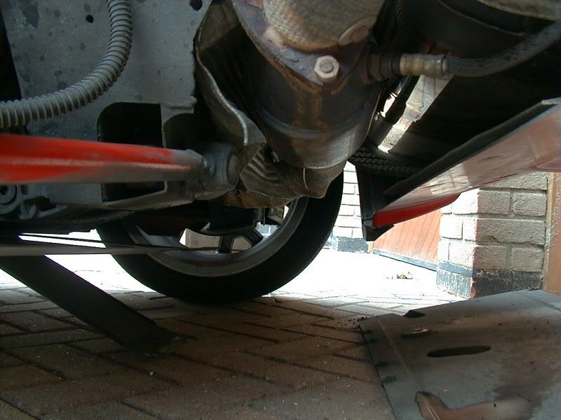
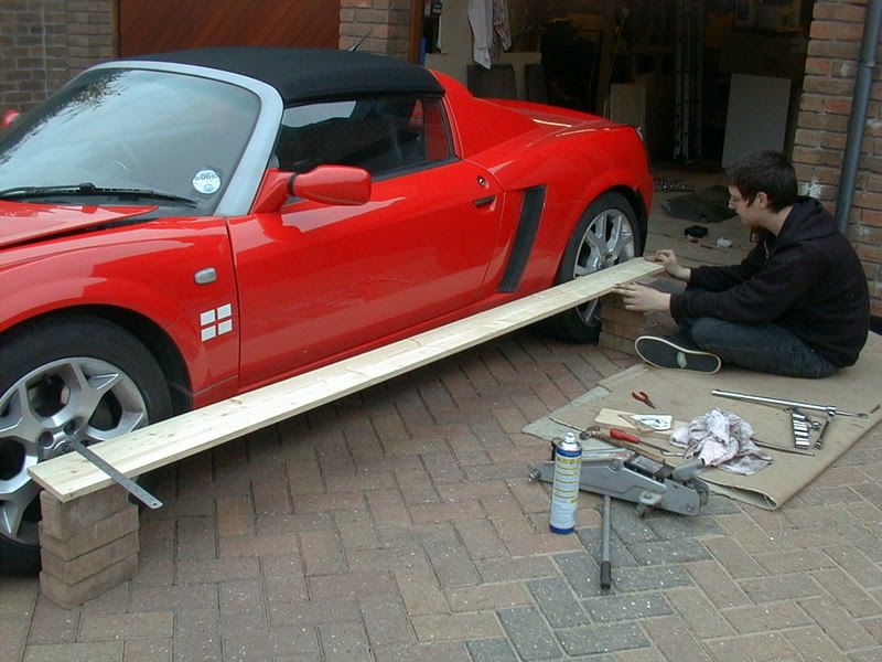
Before removing or changing anything, get a length of wide, planed timber as shown in the picture. By ensuring that the wood touches both the front and the back edge of the rear rim, you can now measure to a datum-point at the front of the car. The best place for this is the centre of the front wheel, as this is a point that matters when it comes to steering-geometry.

Posted Image

You’ll see from the second picture, that I’ve had to attach to little blocks of wood to the edge of the plank to ensure that the rim only touches at the front and back rim-edge. I also got my son to put some pressure on the plank to make sure of good contact with the rim.

Posted Image

You now take a reading from the plank–edge to the centre of the front wheel, using a steel-measure. Get the idea?

You only need to do the side that you’re changing the track-control arm on, but I did both for interest. Oh, and stand the plank on a pile of bricks as per the picture – don’t try to just hold it in place. Jiggle the plank gently to ensure that it overcomes any friction between the plank and bricks.


Posted Image

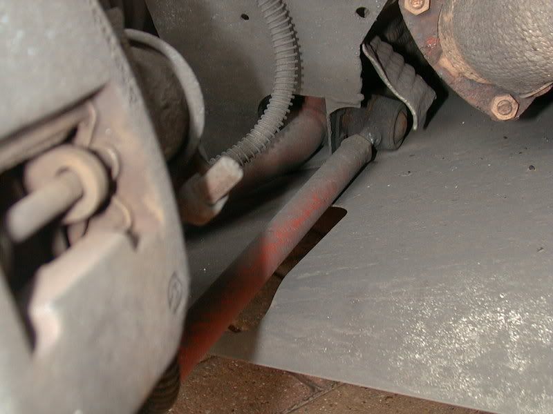
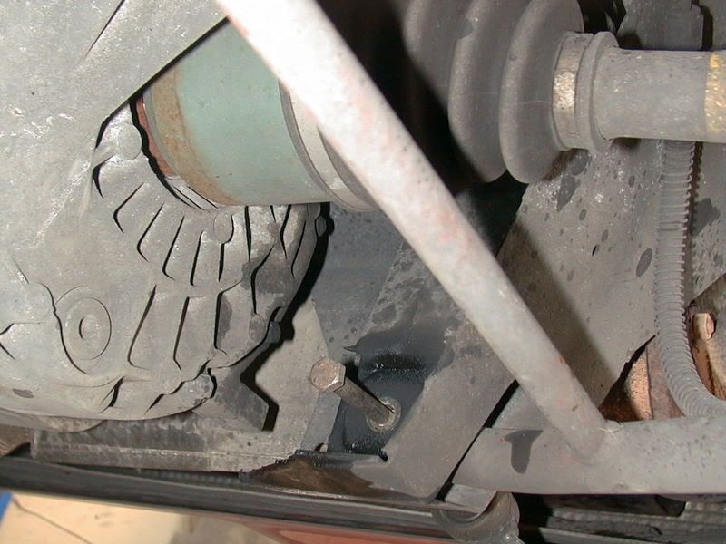
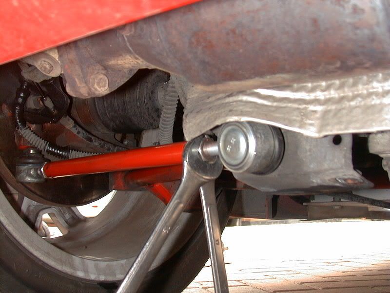
Here’s the old arm in-situ. You can see why the inner ball-joint dries out – it’s very close to the exhaust.

Posted Image

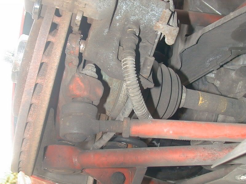
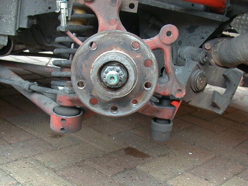
Here’s the outer-end. You can see the outer ball-joint connected to a trailing-arm part of the hub-casting.

Posted Image

Right. Now remove the undertrays.

Posted Image

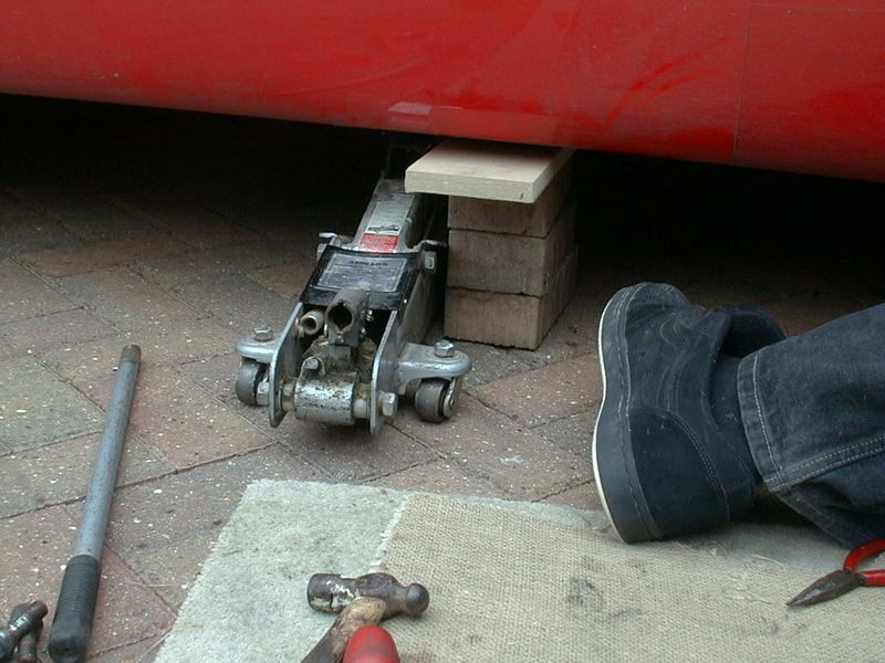
And make sure the car is supported properly – not just a jack. You’ll be lying under the car for some of it…

Posted Image

Remove the brake-calliper – which is as per the instructions for changing the brake-pads.

Posted Image

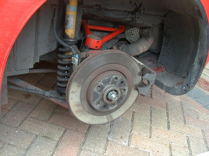
And remove the actual brake-disk. It’s only held on with a single allan-screw.

Posted Image

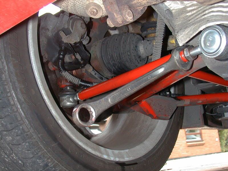
Time to remove the old track-control arm. Use some WD40 to ensure things come off easier. Undo the nut on the end of the ball-joint stem. This stem goes through the back of the chassis, through the rear joint of the lower wishbone, and out the front-side of the chassis. Tap the ball-joint out by using an old bolt of almost the same diameter. That way, the old bolt will keep the wish-bone located.


Posted Image


Then remove the outer ball-joint making note of where the washers and spacers go. The old track-control arm can then be fully removed from the car.


Now to fit the new arm. Screw the new ball-joints in and out of the new arm to make it roughly the same length as the old one – but don’t worry too much about accuracy. Also note that one ball-joint has a left-hand thread and the other has a normal right-hand thread – you’ll understand why later on.

Fit the new arm to the car in the time-honoured way. Note: - the two flats on the body of the inner ball-joint locate on positioners on the chassis to stop it turning. Do the ball-joint mountings up tight.

Put the brake disk and callipers back on and refit the wheel without putting all the under-tray stuff on just yet. Lower the car back onto the ground.


The reason for the left-hand thread and right-hand thread on the two ball-joints, is that if you now rotate the track-control arm in one direction the shaft will grow in length. If you turn it in the other direction then it’ll get shorter. You’ll be surprised how many people don’t suss this out, and try adjusting the length by turning one ball-joint a full rotation.

Posted Image

Get the plank and bricks out and re-adjust the tracking of the wheel.

Posted Image

When finshed, lock the locking-nuts up by using two spanners.

Posted Image


Now you can either put the undertray back on, or go and do the other side.


The usual warning. This is intended as a guide only, and if you don’t have the ability, then don’t attempt this. On a grade of 1-to-10 for ease of doing, I’d rate it pretty easy if you take the time and car. It took my son Ben and I about two hours to do one side.


All done!!!!


Steve

#2 Baron Von Scubadaddy

Baron Von Scubadaddy

    STAGE 3.333333333333333333333333333333

  • PipPipPipPipPipPipPip
  • 6,641 posts
  • Gender:Male
  • Location:North London
  • Interests:Girls, Cars,..... ! spending time asking questions about why my car won't work

Posted 26 May 2007 - 06:53 PM

Nice one looks like an ok job to do chinky chinky

#3 slindborg

slindborg

    The Bishop of Stortford

  • PipPipPipPipPipPipPipPip
  • 22,602 posts
  • Gender:Not Telling
  • Location:.

Posted 26 May 2007 - 11:16 PM

you git, where did you get a new Tie bar setup from?!?!?!? :P they are on major back order at the moment :( good guide thumbsup is the disc + caliper off "vital"?

#4 Winstar

Winstar

    Scary Internerd

  • PipPipPipPipPipPip
  • 4,264 posts
  • Gender:Male
  • Location:Chesterfield

Posted 27 May 2007 - 06:42 AM

Good guide thumbsup

is the disc + caliper off "vital"?


Top Guide Steve.

The nut on the out board end is a right tw@t to get to with out taking the caliper off, you can just get a spanner on it but I couldn't get enough force on it to undo it and you can't get the caliper off without taking the disk off.

Steve a quick note incase anyone hasn't read somewehere else the nut on the inboard end is now a fine pitch M10x1.25 so you may not be be able to reuse the nut.

Edited by Winstar, 27 May 2007 - 06:54 AM.


#5 luna_s

luna_s

    Billy No Mates

  • PipPipPipPipPip
  • 1,934 posts
  • Gender:Male
  • Location:North East Of England

Posted 27 May 2007 - 07:03 AM

nice guide steve, needs to be a sticky, could come in very handy thumbsup

#6 vocky

vocky

    Moderator

  • 11,969 posts
  • Gender:Male
  • Location:Earth

Posted 27 May 2007 - 07:07 AM

ditto thumbsup

#7 cragpuss

cragpuss

    Super Member

  • PipPip
  • 312 posts
  • Location:Staffs

Posted 27 May 2007 - 09:44 AM

Good guide thumbsup But tell me more about the Astra sxi front wheels :blink:

#8 Steve Crisp

Steve Crisp

    Billy No Mates

  • PipPipPipPipPip
  • 1,810 posts
  • Location:Little Ann, Andover, Hants, UK
  • Interests:VX220's...

Posted 27 May 2007 - 09:46 AM

Thanks all, I've had these tie-rods for a while now. I decided to gather a complete set of wishones and tie-rods about two years ago. I'm pretty close to having at least one complete car (in bits) in the loft of my garage! Yes, be careful of the thread for the ball-joints. The ones that were on my car originally had what looks like a standard metric thread, not this M10x1.25 one. You are unlikely to be able to reuse the nuts from the old ones. My own view is that you have to remove the brake caliper to do the job properly. It seriously doesn't take five minutes to remove if you've been doing the brake-pad replacement before. Steve

#9 mandarinvx

mandarinvx

    King of First Replies

  • PipPipPipPipPipPipPipPip
  • 12,621 posts
  • Gender:Male
  • Location:West Mids / Oxfordshire

Posted 27 May 2007 - 10:31 AM

Great guide thumbsup

Good guide thumbsup But tell me more about the Astra sxi front wheels :blink:

There's loads on ebay at the mo, go for pretty cheap too, tho you'll need to add a set of spacers. Size is 205x55x16 standard, tho of course you could put 50's on

#10 Steve Crisp

Steve Crisp

    Billy No Mates

  • PipPipPipPipPip
  • 1,810 posts
  • Location:Little Ann, Andover, Hants, UK
  • Interests:VX220's...

Posted 27 May 2007 - 11:23 AM

Ah the front wheels -sorry! Yes, they fit fine - but you'll need 6mm spacers. I run them with 195/55/16 Toyo T1-R proxys. You might found that the 205 rubber touches the wheel arches at full lock. You can get four Astra rims for around £120 - probably with pretty good rubber on them. Steve

#11 snoopstah

snoopstah

    Scary Internerd

  • PipPipPipPipPipPip
  • 3,056 posts
  • Gender:Male
  • Location:Vancouver, BC

Posted 27 May 2007 - 07:16 PM

Myself (and I think at least one other person) has had a tie-rod fail - in my case, it was at the chassis end, where the threading inside the actual rod appeared to strip itself. My suspiscion was that it was caused by the nut at the chassis end not being tightened up to the rod thoroughly. This meant the balljoint thread was forced against one side of the rod thread and back against the other when you go round corners, eventually causing the rod thread to pull out. Anyway, upshot is, I'd recommend making sure you tighten these up well, as the vibrations the suspension components must have to endure could cause even an averagely-tight nut to work loose. Superb guide though - mine went to Vauxhall to be fixed (fortunately no damage other than the broken tie-rod), but I'd feel quite confident in replacing it myself after reading this.

#12 Anarchy

Anarchy

    Scary Internerd

  • PipPipPipPipPipPip
  • 2,237 posts
  • Gender:Male
  • Location:W yorks

Posted 27 May 2007 - 07:49 PM

Got a tie rod kit from Autovaux about a week ago, he did say they were hard to get. Gonna change mine soon, I was going to just measure the length of the old one and make the new one the same length? Putting a new steering rack on too, when its all done a geo will be done.

#13 Steve Crisp

Steve Crisp

    Billy No Mates

  • PipPipPipPipPip
  • 1,810 posts
  • Location:Little Ann, Andover, Hants, UK
  • Interests:VX220's...

Posted 27 May 2007 - 09:45 PM

Comparing length of the new with the old gives you a good starting point Anarchy, but even small increments of a turn make a difference to your tracking. It's not going to work well that way. Still, it'll be close enough for a short while until you can get it set-up correctly... Steve


0 user(s) are reading this topic

0 members, 0 guests, 0 anonymous users