If you are happy with your existing tracking setup you might want to make this little device first which I guarantee will save you time and the cost of having your tracking checked afterwards.
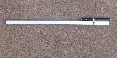
Pop onto eBay and buy one of those cheap laser pointers, you should manage that for under a fiver. Then get yourself something rigid to mount it on, I used a bit of U-channel aluminium from B&Q. Cut the channel to length (I’m assuming you went for the same as me) so it spans the rim of a front wheel.
Put the pointer on top of the channel and make sure that the beam is roughly parallel to the channel, no need to be too accurate – the beam usually comes out of the pointer at a slight angle so rotating the pointer is an easy way to make the adjustment. Strap the pointer firmly to the channel with something like tywraps or jubilee clips, it’s crucial that nothing moves when you start using it so I used hot melt glue just to make sure. Arrange for the laser to stay on, I did this by just pushing the button in and forwards until it stuck on then you can unscrew the battery cap at the bottom to turn it on and off.
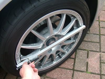
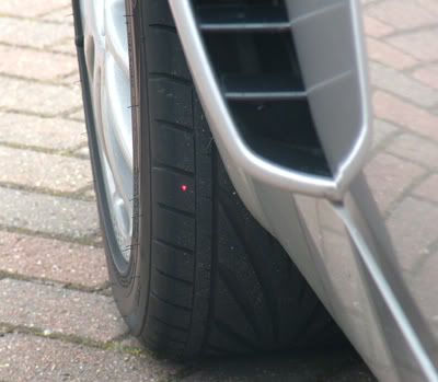
To record your current wheel alignment, park your car about 20 feet from a wall or garage door at a right angle – the further back the more accurate the measurement will but I reckon 15+ feet is fine, with the wheels straight ahead. Mark the ground with the position of one of the wheels so you can put the car back to the same distance later. Put the channel on the first wheel rim, hold it horizontal and level with the wheel centre.
Have an accomplice mark the point on the wall / door where the spot lands then do the same with the other wheel.
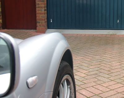
That’s it, when you have finished with the rack, you can put the car back in the same place and when your wheel alignment is correct your dots will be the same distance apart as your marks.
Things you’ll need to swap the rack
An inspection lamp / torch
13mm & 17mm sockets
Molegrips
2x 13mm spanners (or one and the socket)
X, x and x Open ended spanners
A large flat screwdriver
2x smallish flat or Phillips screwdrivers
A hammer
A Jack
Your wheel key and wheelnut spanner
Sticky tap
2 new Nylock nuts for the track-rod ends
2 new 13mm Nylock nuts for the intermediate shaft bolts (or not depending on what sort of fixing you find)
2 Plastic carrier bags
4 bits of cardboard about 10" square
Washing up liquid
Radox Muscle Soak Herbal Bath
Tea
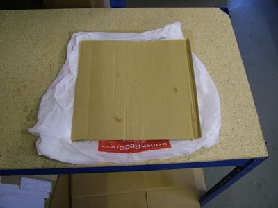
Before you start make a couple of these to make moving the wheels easier. Get a nice thick plastic carrier bag, M&S ideally, Tesco as a last resort. Sprinkle some washing up liquid inside the bag
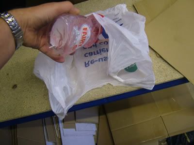
Sandwich the bag between 2 bits of cardboard, then make another one exactly the same. Put one under each front wheel and a 2 year old will be able to turn the steering wheel with the car stationary.
1. Put the handbrake on
2. Turn the steering wheel fully clockwise
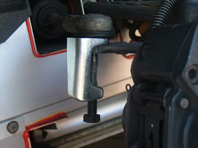
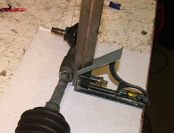
3. Look in the LH wheel arch, you can see the track-rod end easily enough. Undo the nut with a 17mm socket. Tap (don’t bang) the track rod end from underneath with a hammer and it should pop out. If you are swearing already one of 2 things has happened.. either the track rod end came loose early and the nut is just rotating the threaded portion, in this case clamp the track-rod end to the arm with a pair of Molegrips, now you’ll be able to undo the nut... or... tapping was fun but the track-rod end didn’t come out. If this was a Mondeo you would be going to look for a bigger hammer about now, but resist. Use a splitter if you have one or go and buy the cheap screw based splitter from Halfords (pictured below) for £7.99 if you don’t.
4. Jack the RH side of the car up and remove the front wheel.
5. Undo the Track-rod end nut and separate the joint as in 1.
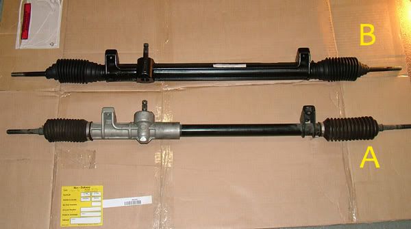
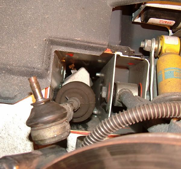
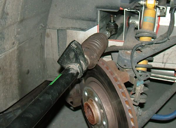
6. Take a look in the rack tunnel and see which of these 2 racks you have. a. Rack 'A' will come straight out with no problems at all as the casing under the spigot is narrower. With rack 'B' you might be lucky but most likely you’ll spend ½ an hour twisting and swearing and it will still be in there, so..
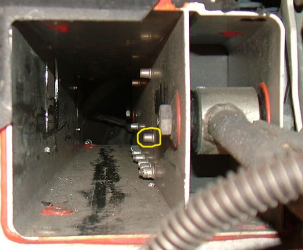
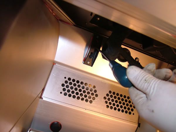
if you have rack 'B' locate the Rivnut circled in the pic below, place the end of your large flat screwdriver at the base and whack the screwdriver with the hammer. The Rivnut isn’t used and as there is no bolt inside it, a couple of decent clouts will snap it off. This will give you plenty of room to extract the rack.
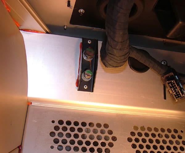
7. Take your 13mm and 17 sockets and the pair of 13mm spanners, sit in the driver’s seat with your legs out of the door and lean under the dash.
8. Marvel at how neatly the handbrake handle fits between your 2nd and 3rd ribs
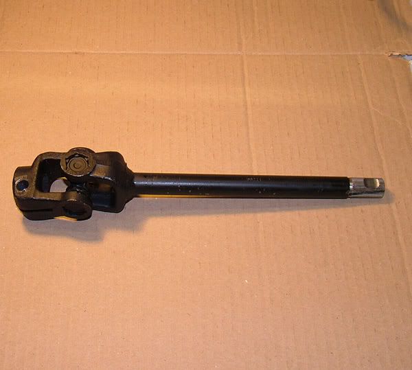
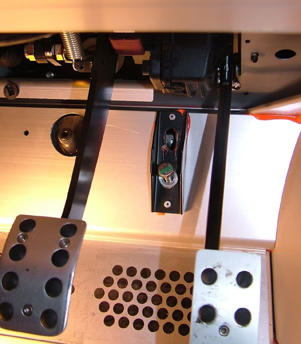
9. Using your 2x 13mm spanners, remove the bolts from the intermediate shaft universal joint(s) between the rack and the steering column. There are 2 types of shaft around, one with 2 joints and a separate shaft like this
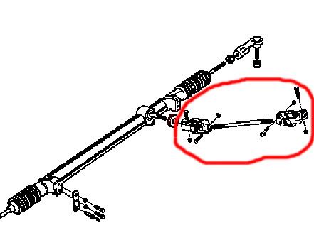
and 1 which has one joint welded to one of the UJ’s as in the pic below, so just remove as many bolts as you come across.
10. Don’t try and get the shaft out yet.
Hit my image limit here so see the next part for the rest...


 Mods come on wake up. Put it in there!!

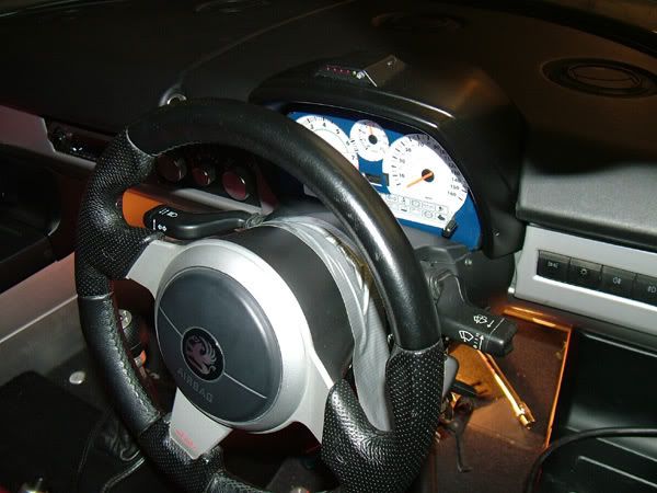
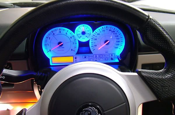
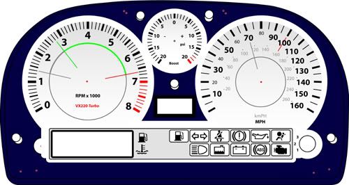
 Need more info about that dash too though - what's the centre dial?


 )
They also offer a refurb service
)
They also offer a refurb service 
 Thanks for saving me tons of hassle.