Hi everybody!
I have to install the new Elise-shop Toe link kit on my VX220NA. I would like to know if it is necessary to lift the car and remove the rear wheels to do the job.
Do you think I can change the toe links by only removing the rear diffuser leaving the wheels at their place?
Any suggestions is accepted. Thanks in advance for your help.
47 replies to this topic
#2

JG
-

-

- 13,617 posts
Newbie
- Gender:Male
- Location:West Berks
Posted 22 December 2012 - 08:25 AM
Wheels off. You can adjust them with wheels on, but fitting is a lot easier with them off
#3
TazN
-

-

- 2,931 posts
Scary Internerd
- Gender:Male
- Location:Suffolk
- Interests:Video Games, Airsoft, American Football, Cars
Posted 11 May 2013 - 03:04 PM
After some fitting advice.
I've got the rear hub back on after suspension refresh, castle nut has been tightened to pull hub into place. The inboard end fits absolutely fine but I'm having trouble lining the outer end up with the hole on the hub. I've fitted the dampers back on, do I need to jack the lower wishbone up to get the right angle for the bolt to thread through the link end and then the hole for the hub?
Currently I can get the link into the hub at a slight angle but obviously the bolt wont go right through. I've tried winding the toe link further out and in but doesn't seem to effect it too much.
Any help appreciated.
#4
Kieran McC
-

-
- 3,416 posts
Scary Internerd
- Gender:Male
- Location:Norwich
- Interests:Fast cars,Track Days.
Posted 11 May 2013 - 03:26 PM
Taz can you post a photo of the part that will not line up?
#5
ghand
-

-
- 9,215 posts
Drunken lampposts only
- Gender:Male
- Location:St helens merseyside
-
Interests:Whisky.Keeping reptiles.Cars.
The odd bike ride, fell walk and weights
Oh and more whisky
Posted 11 May 2013 - 03:50 PM
Strange, I had no problem doing mine.
I marked it all up with a laser spirit level first to save the need for a geo.
Maybe as you say lift the hub,in and out will not alter the angle like up and down will,but should be loads of movement in it ?
Lotusfan, as above just take the wheel of,loads easier.
Edited by ghand, 11 May 2013 - 03:57 PM.
#6
TazN
-
-
- 2,931 posts
Scary Internerd
- Gender:Male
- Location:Suffolk
- Interests:Video Games, Airsoft, American Football, Cars
Posted 11 May 2013 - 03:51 PM
Outside end of the toe link where it goes under the hub. Not sure if it needs to have the suspension compressed by jacking the lower wishbone so the end of the toe link is level with the inboard end which would alleviate the angle difference.
Quick paint to explain what I mean:

#7
Kieran McC
-
-
- 3,416 posts
Scary Internerd
- Gender:Male
- Location:Norwich
- Interests:Fast cars,Track Days.
Posted 11 May 2013 - 03:56 PM
Jack the hub up to get it level,slacken of both the toe link ends it should line up ok then
#8
TazN
-
-
- 2,931 posts
Scary Internerd
- Gender:Male
- Location:Suffolk
- Interests:Video Games, Airsoft, American Football, Cars
Posted 11 May 2013 - 03:59 PM
Excellent, will give that a try as it's finally stopped raining.
#9
Crabash
-

-
- 1,686 posts
Scared
- Gender:Male
- Location:Durham
Posted 11 May 2013 - 10:11 PM
Hmm not so sure about that, if it wont go in as your pic shows then there is something wrong, toe link too short or as you say you tried that the hub carrier is being "blocked" from turning around the wishbone ball joints somehow.
There should be enough sliding movement in the cv joint splines to allow some turning so if it's stopping and your toe links are aprox length of old ones and wont go in then I would say something is wrong.
So even if you got it in I would check nothing is locking or coming to a stop under full droop.
#10
TazN
-
-
- 2,931 posts
Scary Internerd
- Gender:Male
- Location:Suffolk
- Interests:Video Games, Airsoft, American Football, Cars
Posted 12 May 2013 - 02:50 PM
Ok had all kinds of fun and games with those shear brackets. But it does seem to fit spot on if I jack the suspension up slightly. Will see how it all looks when it is back on the ground but once again rain holts play.
After fiddling about all afternoon with these I have another question that doesn't seem to be covered in the instructions. The space between the bracket and subframe which the toe link goes in still has a gap when I fit the toe link end in. I can see torquing this bolt up would just bend/crush the bracket. It comes with 6 bump steer shims, should I be using these to fill in the gap?
#11
Crabash
-
-
- 1,686 posts
Scared
- Gender:Male
- Location:Durham
Posted 12 May 2013 - 03:02 PM
Been a while since I did mine but I don't remember any of these problems, bump steer shims are for the other end. Mine came with a bump steer guide of some kind as I remember it.
#12
TazN
-
-
- 2,931 posts
Scary Internerd
- Gender:Male
- Location:Suffolk
- Interests:Video Games, Airsoft, American Football, Cars
Posted 12 May 2013 - 05:22 PM
Well I assume that's what they are. It's what the kit instructions call them....
I'll get a photo tomorrow, I'm pretty sure there isn't a single part of me that isn't in pain right now :/
#13
TazN
-
-
- 2,931 posts
Scary Internerd
- Gender:Male
- Location:Suffolk
- Interests:Video Games, Airsoft, American Football, Cars
Posted 13 May 2013 - 07:13 AM
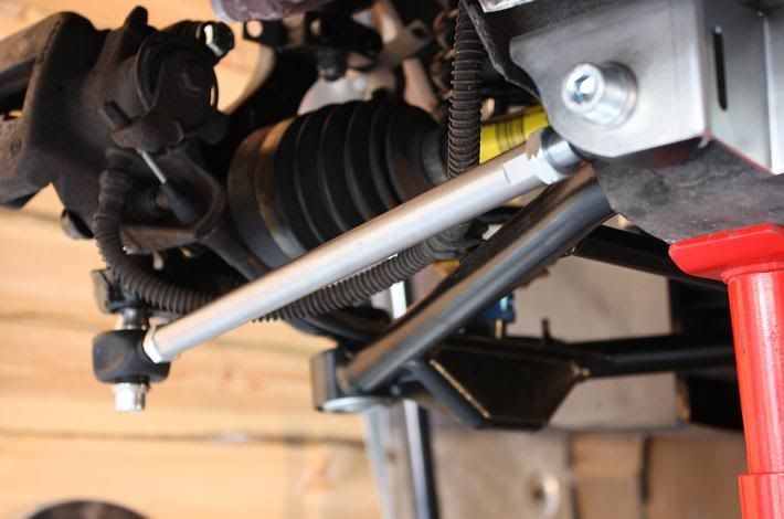
Picture as promised. Toe link isn't connected hub end here but you can see there is 2-3mm of space between the end and bracket.

#14
Arno
-

-
- 1,238 posts
Need to get Out More
- Gender:Male
- Location:Netherlands
Posted 13 May 2013 - 07:31 AM
There should be a spacer with a 'ridge' on it that fits into the slotted washes that's welded onto the sufbrame to take up the space.
BTW.. You may want to add a block of wood under the axle stand.. You're bending the mounting point as far as I can see 
Bye, Arno.
#15
TazN
-
-
- 2,931 posts
Scary Internerd
- Gender:Male
- Location:Suffolk
- Interests:Video Games, Airsoft, American Football, Cars
Posted 13 May 2013 - 08:32 AM
In hindsight I wish I'd bought flat topped stands all round
Really not following you on the first point though Arno. The kit comes with a thicker washer that has a lip on it, this slots into the bracket and the bolt passes through it, the end and then the sub/bush. The only thing I have left are the tapered pieces that are used instead of the conical ones that sits in the hub and these bump steer washers but I can see how they are used hub end.
I have 2 other pieces that are hard to describe but aren't even listed on the kit contents....I've just tried them on the other side and it fits into the bracket but not the sub frame, bolt slides through it fine.

#16
mbes2
-

-
- 8,516 posts
Someone say Plasti Dip?
- Gender:Male
- Location:Feering, Essex
-
Interests:"Keep it standard"
"Yes, I built it"
Posted 13 May 2013 - 08:44 AM
TazN,
Like this

#17
TazN
-
-
- 2,931 posts
Scary Internerd
- Gender:Male
- Location:Suffolk
- Interests:Video Games, Airsoft, American Football, Cars
Posted 13 May 2013 - 08:53 AM
Ok see that makes sense, thanks Mbes. It does completely contradict the instructions though  which say inbound end is symmetrical and the main thing I was using as point of cant get that wrong.
So bolt goes through a normal washer, locating washer, bracket, small rod end, this weird shaped piece, sub frame, washer, nut.
#18
Pidgeon
-

-
- 5,254 posts
Scary Internerd
Posted 13 May 2013 - 09:20 AM
I emailed Yvo after I'd fitted mine to suggest how the confusing instructions could be changed. I still have play in both sides of mine, I've not fited the replacement parts sent to me, I do hope they cure the problem.
#19
TazN
-
-
- 2,931 posts
Scary Internerd
- Gender:Male
- Location:Suffolk
- Interests:Video Games, Airsoft, American Football, Cars
Posted 13 May 2013 - 09:46 AM
The replacement part being the weird shaped piece I've shown above?
Just tried Mbes setup and it was bloomin' tight to get in with next to no play front/back. Just got to switch out the n/s and do it this way now.
#20
siztenboots
-

-
- 26,614 posts
RaceMode
- Gender:Not Telling
- Location:Surrey
- Interests:french maids
Posted 13 May 2013 - 09:54 AM
If I understand EPC correct , then there are 3 types
http://www.speedster... hub/index.html
NA
early Turbo , upto build # 6995
late Turbo , build # 6996 onwards
you fit the insert to the hub as appropriate


2 user(s) are reading this topic
0 members, 2 guests, 0 anonymous users

