Jump to content


Photo

Abs Fault - Fixing Damaged Sensor Cables


  • Please log in to reply
3 replies to this topic

#1 fezzasus

fezzasus

    Whipping Boy

  • PipPipPipPipPipPipPip
  • 7,689 posts
  • Gender:Male
  • Location:Oxford

Posted 07 August 2013 - 10:16 AM

Symptoms


Car develops intermittent or permanent ABS warning. 


Intermittent ABS faults can be located by identifying when the ABS light comes on, for it me it was while applying full lock so I traced it to one of the front wheels. A fault at the rear passenger side wheel will also manifest as a faulty speedometer.


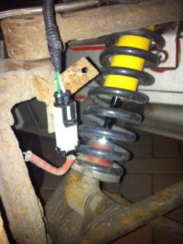
The fault is usually the wire running from the wiring loom to the hub ABS connector. Years of movement, temperature extremes and salt from the roads cause the cable to become brittle and shear at the connector. You can see the location by my previous bodged repair on mine in this photo:


Posted Image


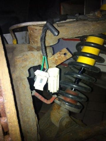
You may need to pull on the cables to see if they are loose, as the insulation may hide the fact that the copper core has broken.


Consumables


    [*]2 way 8 A superseal connector, usually available on eBay for about £2, also available here: http://www.polevolt...._SC2_66KIT.html only the female connector is needed.
    [/list]

    Posted Image


      [*]Solder
      [*]Wiring loom tape
      [*]approx. 5 cm 1.0 mm diameter wire to extend loom
      [*]heat strink
      [*]sand paper (between 120-400 grit)
      [/list]


      Tools


        [*]crimp tool for non insulated connectors
        [*]soldering iron
        [*]wire cutters
        [*]wire strippers
        [*]Small flat head screwdriver
        [/list]

        Repair


        1. Cut damaged wire before damage, cut non-damaged wire at connector to maximise wire length

        2. remove insulation from wire, sand exposed wire as it will have developed a tarnish which prevents the solder from binding the wires together

        3. Solder new wire onto old, cover join with headstrink

        4. remove approx 3-4mm insulation from ends of wire, push on wire seals, crimp terminal in place


        Posted Image


        5. Insert into connector, use a small flat head screw driver to properly seal the terminals and seals.

        6. Use wiring loom tape to seal the end of the trunking.

        7. reconnect ABS sensor


        Posted Image


#2 Rosssco

Rosssco

    Scary Internerd

  • PipPipPipPipPipPip
  • 4,180 posts
  • Gender:Male
  • Location:Aberdeen

Posted 07 August 2013 - 10:21 AM

Good guide. Experiencing these issues currently.


Regarding the connector pins, what crimp tool is required - I tried these before I'm sure and made an mess of them, and couldn't get them to insert properly into the plastic connector housing?


#3 fezzasus

fezzasus

    Whipping Boy

  • PipPipPipPipPipPipPip
  • 7,689 posts
  • Gender:Male
  • Location:Oxford

Posted 07 August 2013 - 10:29 AM

You can use a basic one like this as long as they go down to 1.0 mm: http://www.polevolt....info_TT310.html However I use this: http://www.polevolt....info_TT350.html because it is much easier to position the connector. One thing I would suggest is not crimping the connector over the seal, simply pushing the seal further up the wire. The seal should work the same once seated, it just makes it much easier to crimp the connector.


(you can get both crimp tools on ebay for less - look for a  non-insulated crimp tool that works with 1.0 mm terminals, i'm using these links because they are permanent) 


#4 fezzasus

fezzasus

    Whipping Boy

  • PipPipPipPipPipPipPip
  • 7,689 posts
  • Gender:Male
  • Location:Oxford

Posted 07 August 2013 - 10:30 AM

As for inserting them into the housing, pay attention to the orientation of the terminals, as they will often only go it one way, the terminal may also be distorted by the crimp tool if the one you are using isn't fit for purpose.


0 user(s) are reading this topic

0 members, 0 guests, 0 anonymous users