They do have temp limits
They do give advice where to position them

Innovate Wideband And Fitting
Started by
Bargi
, Jun 26 2014 02:56 PM
39 replies to this topic
#21

CHILL Gone DUTCH
-
-

- 13,727 posts
I ADMIT BATMAN THINKS HE IS QUICKER THAN ME
- Gender:Male
- Location:UK
Posted 26 June 2014 - 08:01 PM
#22
Bumblebee
-

-
- 7,592 posts
.....
- Gender:Female
- Location:York
Posted 26 June 2014 - 08:56 PM
I used to have the innovate and had no problems but I've now got an AEM failsafe gauge might be handy for people who are running aftermarket ecu's unless it's already built in. (Guess it depends how much you trust the failsafe too)
Edited by Bumblebee, 26 June 2014 - 08:57 PM.
#23
Hopegreen
-
-
- 94 posts
Member
- Gender:Male
- Location:Spain
Posted 26 June 2014 - 08:56 PM
I've just instaled the clock and it works
#24
Exmantaa
-

-
- 3,982 posts
Scary Internerd
- Gender:Male
Posted 26 June 2014 - 09:21 PM
They are fine if you understand they have limits and specific requirements for setup
As Arno said, power and ground at the same place the ecu gets it from. And calibrate it in free air as often as you fancy.
If you have a good one they work fine, but if you're unlucky it can/will loose it's calibration randomly. (Despite ecu ground and a dedicated & delayed relay power. => Google LC1...)
Not nice if it recalibrates itself halfway during a calibation session and you can throw your WOT logsession into the wastebin. (not to mention you then have to remove the sensor, again, for a decent re-calibration.  )
)
Edited by Exmantaa, 26 June 2014 - 09:24 PM.
#25
smiley
-

-
- 10,427 posts
Thetan level 15
- Gender:Male
- Location:Netherlands
Posted 26 June 2014 - 09:27 PM
Peter has been running an Innovate since last last year and he said it's been fine.
Peter is running the optional shield thingy on his.
#26
slindborg
-
-
- 22,602 posts
The Bishop of Stortford
- Gender:Not Telling
- Location:.
Posted 26 June 2014 - 09:28 PM
Wish I could remember the portable ones we used at Visteon... Was a blue alloy box and there were trims to set based on the sensors calibration certificate.
#28
Exmantaa
-
-
- 3,982 posts
Scary Internerd
- Gender:Male
Posted 26 June 2014 - 09:48 PM
Peter has been running an Innovate since last last year and he said it's been fine.
Peter is running the optional shield thingy on his.
I would be nice if my LC1 simply reported an error message if there was anything wrong with the sensor temps or whatever, instead of performing a free-air calibration while driving around. 
(I assume they improved now, but just installed a new Tech-Edge wideband today and I cannot justify myself to sell my LC1 on to somebody else...)
#29
oakmere
-

-
- 2,143 posts
Scary Internerd
Posted 26 June 2014 - 11:02 PM
I think the new LC-2 system is meant to be better than the LC1 it replaces. This is only based an internet reading not experience.
#30
Nev
-

-
- 11,587 posts
Nipper's Minion
- Gender:Male
- Location:Bristol
- Interests:Rock climbing, skiing, kayaking, surfing, mountaineering, budgies, chess, practical mechanics.
Posted 27 June 2014 - 08:22 AM
Just do these things and the LC1 will work fine:
1. Earth it correctly (as the instructions say) with good clean contacts.
2. Place the bung on the outside radius of and exhaust bend, far down the exhaust pipe.
3. Calibrate the thing by taking the sensor out of the exhaust pipe and pressing the red reset button.
I disagree with Exmantaa, I see no reason why the kit would "self calibrate itself randomly" in the middle of driving. There is a physical button to perform this process manually.
Edited by Nev, 27 June 2014 - 08:26 AM.
#31
Exmantaa
-
-
- 3,982 posts
Scary Internerd
- Gender:Male
Posted 27 June 2014 - 09:35 PM
Just do these things and the LC1 will work fine:
1. Earth it correctly (as the instructions say) with good clean contacts.
2. Place the bung on the outside radius of and exhaust bend, far down the exhaust pipe.
3. Calibrate the thing by taking the sensor out of the exhaust pipe and pressing the red reset button.
I disagree with Exmantaa, I see no reason why the kit would "self calibrate itself randomly" in the middle of driving. There is a physical button to perform this process manually.
Nev, I will be happy to sell you my LC1 unit for say 75,-?
(That physical calibration button is just shorting the LED wire to ground, but the voltage difference over the LED is not far from the calibration trigger setpoint... I probably have an unlucky one, but if you do a quick google on "LC1 + problem" I would think twice buying it.  )
)
#32
oakmere
-
-
- 2,143 posts
Scary Internerd
Posted 28 June 2014 - 09:38 AM
All the problems seem to be with the lc1 just get the lc2. Can you even buy the lc1 anymore?
#33
davemate
-

-
- 3,228 posts
Harrop!!!
- Gender:Male
- Location:Bath
- Interests:Provoking Badgers
Posted 29 June 2014 - 09:08 PM
I have the heat sync bung on mine, as mentioned above. They can be found cheaper on amazon http://www.amazon.co...5&robot_redir=1
#34
dw1
-

-
- 3,043 posts
Scary Internerd
- Gender:Male
Posted 29 June 2014 - 11:14 PM
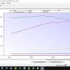
Another vote for the PLX, this is it in situ

Its slim so I stuck it on the dash rather than cut it in. It's not the neatest install but it's non-invasive which is what I wanted.
I like the scrolling graph feature mode as you can look at the trace over time so you don't have to keep your eyes on the gauge in the moment.
What ever gauge make you get, the trace for data logging can be useful when traced against revs or throttle.

The reality is I dont look at the gauge often, but I guess it's there if I think I need it. The ability to log the data gives me peace of mind so that someone more technical than me can make sense of it.
Its slim so I stuck it on the dash rather than cut it in. It's not the neatest install but it's non-invasive which is what I wanted.
I like the scrolling graph feature mode as you can look at the trace over time so you don't have to keep your eyes on the gauge in the moment.
What ever gauge make you get, the trace for data logging can be useful when traced against revs or throttle.
The reality is I dont look at the gauge often, but I guess it's there if I think I need it. The ability to log the data gives me peace of mind so that someone more technical than me can make sense of it.
#35
Mr Apex
-
-
- 320 posts
Super Member
- Gender:Male
- Location:Bristol
- Interests:Karting, climbing, skiing, boxing, cycling
Posted 30 June 2014 - 06:40 PM
The Wideband Lambda is standard Bosch kit. It is not an Innovate product. The wideband sensors are definitely temperature sensitive. If they overheat, they die. Also, if they are exposed to hot exhaust gasses when not powered up, they die. I know, because I read all the comments about it not being necessary to use the extended bungs, decided not to bother and killed a sensor. With the extended bung, the new sensor has been perfect.
The design fault in the Innovate kit appears to be that if the sensor appears to overheat, the Innovate shuts down. Which kills the sensor, even if it wasn't already dead. So it is really important to install the kit correctly, wire it into the correct, interference free power supply and earthing points. If you do, it works perfectly.
#36
slindborg
-
-
- 22,602 posts
The Bishop of Stortford
- Gender:Not Telling
- Location:.
Posted 30 June 2014 - 07:34 PM
Oddly when using the same sensor, but different controllers you don't need the bung.... The lc1 certainly didn't used to adhere to the Bosch spec completely though,
#37
Nev
-
-
- 11,587 posts
Nipper's Minion
- Gender:Male
- Location:Bristol
- Interests:Rock climbing, skiing, kayaking, surfing, mountaineering, budgies, chess, practical mechanics.
Posted 30 June 2014 - 09:11 PM
Just do these things and the LC1 will work fine:
1. Earth it correctly (as the instructions say) with good clean contacts.
2. Place the bung on the outside radius of and exhaust bend, far down the exhaust pipe.
3. Calibrate the thing by taking the sensor out of the exhaust pipe and pressing the red reset button.
I disagree with Exmantaa, I see no reason why the kit would "self calibrate itself randomly" in the middle of driving. There is a physical button to perform this process manually.
Nev, I will be happy to sell you my LC1 unit for say 75,-?
(That physical calibration button is just shorting the LED wire to ground, but the voltage difference over the LED is not far from the calibration trigger setpoint... I probably have an unlucky one, but if you do a quick google on "LC1 + problem" I would think twice buying it.
Okies, I was unaware of this problem.
#38
TheHood
-

-
- 1,036 posts
Need to get Out More
- Gender:Male
- Location:Midlands
- Interests:World domination, a liking of unconvincing disguises, Malaysian temple restoration and nice words like "flange".
Posted 19 August 2015 - 08:01 PM
Thread resurrection alert! I'm fitting a Spartan 2 wideband and I take it from the lack of response to Oakmere's question that no one has expirenced any issues wiring in from a normal switched live rather than one that is only live when the engine is running? Reading my installation instructions it says that there is a risk of thermal shock to the sensor caused by moisture during engine start up if the sensor is already up to temperature. It would make things a lot easier if I could just use the existing narrowband connection to power the wideband.Is it worth taking the switched live from the fuel pump relay, which is only permanently on when the engine is running (apart from the short blip as the pump primes)? As I believe the wide bands don't like being switched on without the engine running.
#39
techieboy
-

-

- 22,914 posts
Supercharger of Doom
- Gender:Male
- Location:Bedford
Posted 19 August 2015 - 08:34 PM
My Spartan is only powered with the engine running via a trigger feed from the fuel pump relay.
#40
TFD
-

-
- 607 posts
Super Duper Member
- Gender:Male
- Location:The Netherlands
Posted 26 August 2015 - 09:39 AM
Did a write-up thread on the dutch forum.:
X2 Blue connector
[color=rgb(51,51,51);font-family:'Lucida Grande', 'Trebuchet MS', Verdana, Helvetica, Arial, sans-serif;font-size:13px;background-color:rgb(236,243,247);]pin 1 = bn/pk (pin 87 of relay K18, +12v for fuel injectors)[/color]
[color=rgb(51,51,51);font-family:'Lucida Grande', 'Trebuchet MS', Verdana, Helvetica, Arial, sans-serif;font-size:13px;background-color:rgb(236,243,247);]pin 2 = wh/bk (instrument - rev counter) + (start relay K24 pin 9)[/color]
[color=rgb(51,51,51);font-family:'Lucida Grande', 'Trebuchet MS', Verdana, Helvetica, Arial, sans-serif;font-size:13px;background-color:rgb(236,243,247);]pin 3 = ?[/color]
[color=rgb(51,51,51);font-family:'Lucida Grande', 'Trebuchet MS', Verdana, Helvetica, Arial, sans-serif;font-size:13px;background-color:rgb(236,243,247);]pin 4 = ?[/color]
[color=rgb(51,51,51);font-family:'Lucida Grande', 'Trebuchet MS', Verdana, Helvetica, Arial, sans-serif;font-size:13px;background-color:rgb(236,243,247);]pin 5 = gn (+12v FuseBox 7)[/color]
[color=rgb(51,51,51);font-family:'Lucida Grande', 'Trebuchet MS', Verdana, Helvetica, Arial, sans-serif;font-size:13px;background-color:rgb(236,243,247);]pin 6 = ?[/color]
[color=rgb(51,51,51);font-family:'Lucida Grande', 'Trebuchet MS', Verdana, Helvetica, Arial, sans-serif;font-size:13px;background-color:rgb(236,243,247);]pin 7 = ?[/color]
[color=rgb(51,51,51);font-family:'Lucida Grande', 'Trebuchet MS', Verdana, Helvetica, Arial, sans-serif;font-size:13px;background-color:rgb(236,243,247);]pin 8 = wh/vt (+12v for relay coil, pin 85 - fuel pump relay K16)[/color]
[color=rgb(51,51,51);font-family:'Lucida Grande', 'Trebuchet MS', Verdana, Helvetica, Arial, sans-serif;font-size:13px;background-color:rgb(236,243,247);]pin 9 = gn/bu (instrument - coolant temp gauge [pulsed signal from ecu])[/color]
[color=rgb(51,51,51);font-family:'Lucida Grande', 'Trebuchet MS', Verdana, Helvetica, Arial, sans-serif;font-size:13px;background-color:rgb(236,243,247);]pin 10 = n/c[/color]
[color=rgb(51,51,51);font-family:'Lucida Grande', 'Trebuchet MS', Verdana, Helvetica, Arial, sans-serif;font-size:13px;background-color:rgb(236,243,247);]pin 11 = n/c[/color]
[color=rgb(51,51,51);font-family:'Lucida Grande', 'Trebuchet MS', Verdana, Helvetica, Arial, sans-serif;font-size:13px;background-color:rgb(236,243,247);]pin 12 = gn/pk (0v for relay coil, pin 85 - ECU relay K18)[/color]
[color=rgb(51,51,51);font-family:'Lucida Grande', 'Trebuchet MS', Verdana, Helvetica, Arial, sans-serif;font-size:13px;background-color:rgb(236,243,247);]pin 13 = bu/gy (0v for relay coil, pin 85 - radiator fan relay)[/color]
[color=rgb(51,51,51);font-family:'Lucida Grande', 'Trebuchet MS', Verdana, Helvetica, Arial, sans-serif;font-size:13px;background-color:rgb(236,243,247);]In combinatie met dit schema:[/color]
Innovate dont want to use [color=rgb(51,51,51);font-family:'Lucida Grande', 'Trebuchet MS', Verdana, Helvetica, Arial, sans-serif;font-size:13px;background-color:rgb(225,235,242);]ECU-RADIO-FUELPUMP-INJ etc.[/color]
[color=rgb(51,51,51);font-family:'Lucida Grande', 'Trebuchet MS', Verdana, Helvetica, Arial, sans-serif;font-size:13px;background-color:rgb(225,235,242);]Instead I used the green #5 wire from the blue connector:[/color]
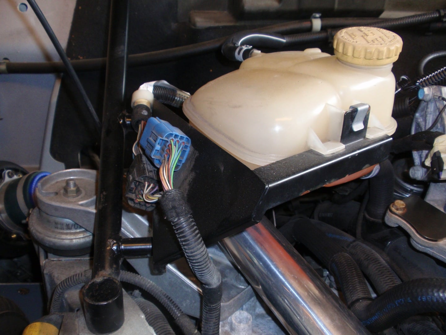
It's a 12V ignition and fuse#7 in the front fusebox. Is also connected for your sideblinkers and fused with a 10A fuse. Innovate wants a 5A fuse so I put a 5A fuse in the signalwire to the wideband. - is connected to the ecu. Works fine so far.


0 user(s) are reading this topic
0 members, 0 guests, 0 anonymous users

