Traction Control Fitting
#1

Posted 11 January 2015 - 05:46 PM
#2

Posted 12 January 2015 - 01:52 PM
My control box is on the engine side of the boot bulhead with the fuse next to it. It's covered by a home made aluminium cover which is earthed (for what it's worth). The ABS wiring runs along the boot wall to the offside wheelarch then down and through the offside sill to the ABS and a switched supply under the dash (can't remember where). The flashing LED is in the sill as I haven't bothered to mount it after set up. I've had no problems with electrical interference and I can only assume that's because of where and how the control box is mounted and how I've run the wires.. Apparently the ABS signals on these cars are poor, and although the unit works fine I can't do a diagnostic of the ABS sensors with the TC, or should I say I can but it won't show a faulty sensor properly although it should.
#3

Posted 12 January 2015 - 09:30 PM
#4

Posted 13 January 2015 - 10:14 AM
My RLTC box sits under the dash with velcro and my digi adjuster is mounted in the dash plate between the radio and the VX220 plate.
Tapping into the ABS is straightforward from this position but the injectors require bringing in wires from the engine bay. The RPM signal comes from the dash.
I have a mini loom made up which includes 5 pairs of cable (1 for each injector and a spare). This follows the main loom into the cabin through the rubber bung behind the rear passenger wheel. It then goes over the fuel tank and into the cabin behind the cup holder trim (again following the original loom). Following this path means dropping the fuel tank, which is a bit of a pain, but it's worth the effort to keep everything well protected. It then runs past the handbrake and gear linkage, through the centre tunnel and up into the dash.
You can avoid dropping the fuel tank if you follow the gear cables through into the engine bay. This is much simpler, and is how mine was originally installed. It ran link this for years without problems, but I decided to re-route everything when I did my rebuild.
Mine was originally installed by buchos and has since been fully re -nstalled by me to make improvements over the original design. You can read all about his install here, along with him addressing concerns people may have with how clean the signals are from the injectors when using 3m of cable (spoiler, it makes no difference at all). http://www.vx220.org...action-control/
Unlike oblomov I have no issues with the ABS readings and the whole system works flawlessly.

Edited by Gedi, 13 January 2015 - 10:18 AM.
#5

Posted 14 January 2015 - 02:54 PM
Thanks for the post and this is what I'm looking for. Do you have a filter fitted near the abs?
See my P.M.
#6

Posted 14 January 2015 - 03:22 PM
You can always add a filter later. If you have the digital adjuster you will see spikes at low speed, signal will get better when speed increases. With a filter mounted, the signal will be good at lower speeds also.See my P.M.Thanks for the post and this is what I'm looking for. Do you have a filter fitted near the abs?
Edited by manus, 14 January 2015 - 03:49 PM.
#7

Posted 09 January 2016 - 11:43 PM
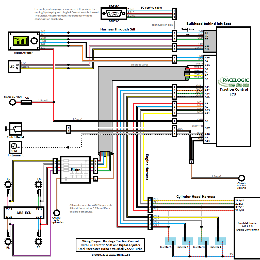
I've just started to have ago at fitting my traction control now and I'm a bit lost with it all. I started unwrapping the cloth tape from each of the injector plugs and the two wires that come off each injector is green and yellow and not the same colour as on this diagram

Before I start pulling the cloth tape off the ecu wires can anyone point me in the right direction of which plug on the ecu it is or have any pictures that could help? I hate wiring 😀
#8

Posted 10 January 2016 - 02:58 PM
Isn't the colouring down to the colour of the wire used to extend the harness when supercharging? You'll need to chase the wiring loom back until you get the right colour.
#9

Posted 10 January 2016 - 03:53 PM
#10

Posted 10 January 2016 - 04:36 PM
#11

Posted 10 January 2016 - 06:31 PM
Edited by manus, 10 January 2016 - 06:47 PM.
#12

Posted 10 January 2016 - 06:58 PM
Advice is to use connectors on your wiring in such a way (male/female female/male) that you can take the TC out of the loop. (Useful in case a wheel sensor or other problem occurs and you wanna get home).
Other problems maybe but with a broken wheel sensor or wheel sensor problems you just switch the TC off.
#13

Posted 10 January 2016 - 08:05 PM
Wiring should go ecu-tc-injectorsJust to double check I've got this right? All I'm doing is adding the extra wires from the TC onto the existing injectors wire? All I have done is where the extra cable was needed for the injector is tap into the old solder and add it that way. Just wanted to make sure I don't just have the wire from the TC straight to the injectors.
#14

Posted 11 January 2016 - 12:11 AM
#15

Posted 11 January 2016 - 04:00 PM
Going to wire two males and female plugs to the wire so I have the option of reverting back to standard if needs be. Next stage after that is abs wiring 😀
That's what I did, but completely forgot (8/9 years ago now) till you mentioned it otherwise I'd have suggested it in my PM. ![]()
#16

Posted 11 January 2016 - 05:18 PM
#17

Posted 11 January 2016 - 07:37 PM
With my datalogger where I broke into existing circuits and didn't want to risk dicking with the electrical values by adding further connectors etc, I just carefully stripped off the insulation where I wanted the join and added the new wire and soldered it. Then covered the splice with Liquid Electrical Tape to make sure it was insulated and sealed from the elements.
http://www.frost.co....rical-tape.html
#18

Posted 11 January 2016 - 07:40 PM
Perfect 👍 Will have to find this liquid electrical tape.With my datalogger where I broke into existing circuits and didn't want to risk dicking with the electrical values by adding further connectors etc, I just carefully stripped off the insulation where I wanted the join and added the new wire and soldered it. Then covered the splice with Liquid Electrical Tape to make sure it was insulated and sealed from the elements. http://www.frost.co....rical-tape.html
1 user(s) are reading this topic
0 members, 1 guests, 0 anonymous users


