It should "fail" exactly the way that it did.
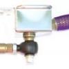
In the first diagram below, the force (in red) is exerted along the toe-link to the ball joint. The ball joint resists this force by holding laterally in single shear with the mounting bolt (the blue lines). But part of the force exerted on the ball joint acts as a rotational moment around the ball joint. That is resisted as a torque (bending) of the ball joint mounting stud. The premature failure of the inner ball joint happens when the ball joint mounting stud is not tight - this allows the mall joint to move around and causes the mounting bolt to dynamically bend back and forth causing the bolt to fatigue and fail.
But the designed in "failure mode" is shown in the second diagram below. In this case, the force on the toe-link is greater than it should be (due to impact). The bending moment about the ball joint is greater than the strength of the threaded connection between the ball joint and the toe-link rod, causing that threaded section to yield (bend). When the force exceeds the ultimate strength of that section, it breaks, stopping the force from being transfered to the chassis by the ball joint. The ball joint fails, and the chassis is undamaged.
In the third diagram, the double shear joint is shown. Again, the force is in red, exerted along the toe-link rod. But there is not bending moment about the Heim joint at the chassis mount. The force is exerted laterally by the rod and resisted latterly by mounting bolts and brackets. There is no bending moment. The result is that if the force along the toe-link rod is too great (as from an impact), that force will be completely transfered to the chassis. There is no part that will bend and fail before transferring that load to the chassis. There is no sacrificial part. The joint is stronger, but the failure mode transfers the damage to the chassis.
fig 1 -

fig 2 -

fig 3 -


