Ian is your crank just held on with a crown nut? Maybe it has a woodruff key in it too that you need to take off. Best check, because it sounds like you are putting an amzing amount of torque on it without it coming off...
Project Itbs
Started by
yaaan
, Apr 14 2012 10:57 PM
28 replies to this topic
#21

Nev
-

-

- 11,587 posts
Nipper's Minion
- Gender:Male
- Location:Bristol
- Interests:Rock climbing, skiing, kayaking, surfing, mountaineering, budgies, chess, practical mechanics.
Posted 19 April 2012 - 07:44 AM


#23
yaaan
-
-
- 956 posts
Need to get Out More
- Gender:Male
- Location:Bristol
Posted 30 April 2012 - 07:57 PM
I've been very slack and not updated this but mainly because I got carried away with getting it finished which it is now, sort of.
Removing the crank sprocket proved to be a bigger job than anticipated as it's bolted on damn tight! This is the bugger:

Not a lot of room to get in there but eventually it was just a case of getting a long extension bar on there, grabbing hold of the wishbone and with my foot on the bar, hulking out. I couldn't get it undone and was getting increasingly frustrated and some carefully channeled rage was all that it took!
Once the pulley was off I noticed that the alternator belt had a few cracks so took the opportunity to replace this. Another lesson learnt at this point: 5mm difference in belt length makes a huge difference. The local Vauxhall stealer gave me an 875mm instead of 880 and I couldn't get the damn thing on and wasted a few hours trying. Took it back the next morning and bought the correct length from a local motor factor and it went on in a matter of minutes!
Once the pulley was off the new crank sensor disc needs to be attached to the pulley. This fits on with three bolts into the three theraded holes on the front of the pulley. They just needed retapping to get the rust out. No pictures of this unfortunately but instructions were provided with this part of the kit and it's quite obvious what goes where. The important bit is to make sure that before removing the pully piston 1 is TDC and that when you reinstall the pulley, the TDC mark on the new sensor wheel is at 6 o'clock, directly above the new crank sensor.

The new crank sensor uses the two lower oil pump cover bolts. The old ones are simply removed and then replaced with spacers and longer bolts. It bolts in place with the bracket pointing away from the engine and mounts downwards. There should be approximately a 1mm gap between the sensor and the teeth on the trigger wheel. It should not touch or be further than 1mm away from the sensor.
Removing the crank sprocket proved to be a bigger job than anticipated as it's bolted on damn tight! This is the bugger:
Not a lot of room to get in there but eventually it was just a case of getting a long extension bar on there, grabbing hold of the wishbone and with my foot on the bar, hulking out. I couldn't get it undone and was getting increasingly frustrated and some carefully channeled rage was all that it took!
Once the pulley was off I noticed that the alternator belt had a few cracks so took the opportunity to replace this. Another lesson learnt at this point: 5mm difference in belt length makes a huge difference. The local Vauxhall stealer gave me an 875mm instead of 880 and I couldn't get the damn thing on and wasted a few hours trying. Took it back the next morning and bought the correct length from a local motor factor and it went on in a matter of minutes!
Once the pulley was off the new crank sensor disc needs to be attached to the pulley. This fits on with three bolts into the three theraded holes on the front of the pulley. They just needed retapping to get the rust out. No pictures of this unfortunately but instructions were provided with this part of the kit and it's quite obvious what goes where. The important bit is to make sure that before removing the pully piston 1 is TDC and that when you reinstall the pulley, the TDC mark on the new sensor wheel is at 6 o'clock, directly above the new crank sensor.
The new crank sensor uses the two lower oil pump cover bolts. The old ones are simply removed and then replaced with spacers and longer bolts. It bolts in place with the bracket pointing away from the engine and mounts downwards. There should be approximately a 1mm gap between the sensor and the teeth on the trigger wheel. It should not touch or be further than 1mm away from the sensor.
#24
DarrylB
-

-
- 1,629 posts
Billy No Mates
- Gender:Male
- Location:Just outside Uxbridge
Posted 30 April 2012 - 08:12 PM
good to see she's up and running :-)
#25
Tom220SC
-

-
- 1,820 posts
Whiiiiine Addiction
- Gender:Male
- Location:Manchester
- Interests:Cars, Football, My VX220.
Posted 30 April 2012 - 10:19 PM
Looking good should sound nice!
#26
yaaan
-
-
- 956 posts
Need to get Out More
- Gender:Male
- Location:Bristol
Posted 01 May 2012 - 11:23 AM
Next up is the plumbing and wiring. To someone with a more expert eye than mine most of this may be quite obvious but it required a fair amount of double checking with Vocky to get this right although none of it is complicated. Once I'd identified all the relevant parts and worked out what connected where it was just a case of fitting them in and tidying up.
First up was the fueling. The old fuel lines needed to be mostly removed and replaced. The line out of the fuel filter is replaced completely with new piping and is much simpler than the old:
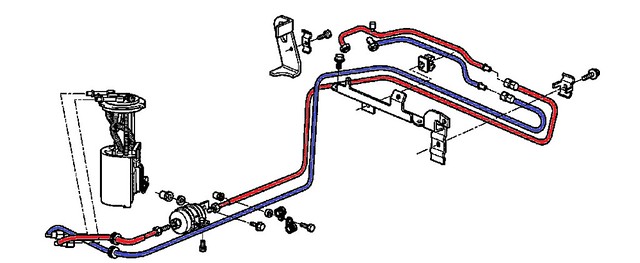
The red pipe is removed, an adaptor connected to the filter and then a short length of hose runs up to the new fuel rail. None of this unnecessary routing and doubling back on itself.

The other end of the fuel rail then connects to the new fuel pressure regulator

before a final pipe runs from the base of this to the old fuel return line which was cut off part way up the vertical section by the bulkhead in the first picture. Much simpler and neater than the old arrangement. There are a couple of other pipe routings that can be improved as well to make things tidier and simpler.
The fpr is mounted just below the window approximately above the alternator. This involved removing the parcel shelf and speaker panel which I wasn't looking forward to but turned out to be much easier than I'd expected although it's a pain in the arse having to take the seats and harness bar out every time so learn from my mistakes and make sure that you've completely finished before you put it all back together again and then have to take it apart again!
There's a handy little ledge on the bulkhead to mount the fpr

so just a case of drilling a couple of holes through the bulkhead. Interestingly every time I needed to drill a hole it was in such a position that the drill could never quite attack straight so always had to go in at a slight angle but this is fine if you don't look too closely
First up was the fueling. The old fuel lines needed to be mostly removed and replaced. The line out of the fuel filter is replaced completely with new piping and is much simpler than the old:
The red pipe is removed, an adaptor connected to the filter and then a short length of hose runs up to the new fuel rail. None of this unnecessary routing and doubling back on itself.
The other end of the fuel rail then connects to the new fuel pressure regulator
before a final pipe runs from the base of this to the old fuel return line which was cut off part way up the vertical section by the bulkhead in the first picture. Much simpler and neater than the old arrangement. There are a couple of other pipe routings that can be improved as well to make things tidier and simpler.
The fpr is mounted just below the window approximately above the alternator. This involved removing the parcel shelf and speaker panel which I wasn't looking forward to but turned out to be much easier than I'd expected although it's a pain in the arse having to take the seats and harness bar out every time so learn from my mistakes and make sure that you've completely finished before you put it all back together again and then have to take it apart again!
There's a handy little ledge on the bulkhead to mount the fpr
so just a case of drilling a couple of holes through the bulkhead. Interestingly every time I needed to drill a hole it was in such a position that the drill could never quite attack straight so always had to go in at a slight angle but this is fine if you don't look too closely
#27
yaaan
-
-
- 956 posts
Need to get Out More
- Gender:Male
- Location:Bristol
Posted 01 May 2012 - 11:40 AM
Next up is the new ecu. I'd been advised to tuck this away down on the passenger side of the bulkhead. There's plenty of room for it here and access is fairly good once the wheel arch has been removed...or folded out of the way in this case as the screws holding it in weren't coming out without a fight I couldn't be bothered with.
I got hold of a right angled piece of aluminium from B&Q in the end, cut a couple of sections for this for the mounts for the ecu and then in was just a case of drilling appropriate holes through the bulk head. Another interesting fact is that drill bits don't go through the black material mounted to the bulk head (sound proofing?). They get all bunged up with fibres so it's probably best to cut holes through this firts before attempting to drill anything. Whilst doing this I also discovered some handily located captive nuts on the inside of the bulkhead, one of which was pressed into action to hold the relays/fuses for the new loom.


Now you can replace all of the interior panelling although subsequently finding that in the process you've killed the speaker connections is a bit of a pita! Haven't found the motivation to take it all apart again to fix that for now but think I can make do with listening to the ITBs for a bit.
Pretty much all of the connections on the loom are labelled so it's not difficult to work out where they connect to. There are one or two that weren't labelled but fortunately the connections they plugged into were significantly different so no danger of plugging them into the wrong sockets. The only two that caused a bit of confusion were these:

Neither were labelled and both exactly the same connector so I wasn't sure which connected to the blue connector and which to the th black but I noticed that the new black connector only had blue and brown cables and only the old black connector had the same so guessed these two joined together and this turned out to be correct.
The only problem running the cables was that the 'inertia' cable that goes to the fuel cut off switch wasn't long enough so I had to make an emergency dash to Halfords for a bunch of connectors and electrical cable.
I got hold of a right angled piece of aluminium from B&Q in the end, cut a couple of sections for this for the mounts for the ecu and then in was just a case of drilling appropriate holes through the bulk head. Another interesting fact is that drill bits don't go through the black material mounted to the bulk head (sound proofing?). They get all bunged up with fibres so it's probably best to cut holes through this firts before attempting to drill anything. Whilst doing this I also discovered some handily located captive nuts on the inside of the bulkhead, one of which was pressed into action to hold the relays/fuses for the new loom.
Now you can replace all of the interior panelling although subsequently finding that in the process you've killed the speaker connections is a bit of a pita! Haven't found the motivation to take it all apart again to fix that for now but think I can make do with listening to the ITBs for a bit.
Pretty much all of the connections on the loom are labelled so it's not difficult to work out where they connect to. There are one or two that weren't labelled but fortunately the connections they plugged into were significantly different so no danger of plugging them into the wrong sockets. The only two that caused a bit of confusion were these:
Neither were labelled and both exactly the same connector so I wasn't sure which connected to the blue connector and which to the th black but I noticed that the new black connector only had blue and brown cables and only the old black connector had the same so guessed these two joined together and this turned out to be correct.
The only problem running the cables was that the 'inertia' cable that goes to the fuel cut off switch wasn't long enough so I had to make an emergency dash to Halfords for a bunch of connectors and electrical cable.
#28
yaaan
-
-
- 956 posts
Need to get Out More
- Gender:Male
- Location:Bristol
Posted 01 May 2012 - 11:55 AM
Before mounting the new manifold in place, the old injector holes need to be blanked off. There are four plugs provided as part of the kit. These are little cap shaped items that fit nicely over the end of a 10mm socket so I used one of these plus a short extension bar to locate them in the holes and then used a hammer to tap them gently in to place. It's also worth covering the inlet ports just to make sure nothing drops in them (I dropped one of the injector O rings through the injector hole on removal and spent ages fishing the bugger out so thsi is worth bearing in mind)
As I discovered yesterday, I didn't however tap them in tightly enough and blew one out. Having spoken to Webcon to get some more they advised adding a bit of Araldite to the plugs when fitting them.
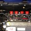
Next up was mounting the manifold. O rings are supplied so making sure they were set in correctly I got the manifold lined up and in place

Finally it looks like wer're making progress The loom can now be attached to the appropriate connectors as can the servo hose to the manifold, and the fuel lines.
At this point I also shortened the return hose to the coolant reservoir. Previously this ran from the engine block to the bulkhead, across that and then back out to the reservoir. As Vocky pointed out though, this is obviously carrying hot coolant so will heat the air around the intake so following his advice it was redirected across the top of the manifold. this should help to keep the air a little cooler around the intake and also serves to tidy the engine bay up a little bit.
Also, the breather hose that previously ran parallel to this retunr pipe has been shortened so no feeds directly from the carbon filter to the driver's side ear/vent rather than running unnecessarily across the bulkhead to the passenger's side. Eveything looks much tidier now and plenty of room for future additions.
As I discovered yesterday, I didn't however tap them in tightly enough and blew one out. Having spoken to Webcon to get some more they advised adding a bit of Araldite to the plugs when fitting them.
Next up was mounting the manifold. O rings are supplied so making sure they were set in correctly I got the manifold lined up and in place
Finally it looks like wer're making progress
The loom can now be attached to the appropriate connectors as can the servo hose to the manifold, and the fuel lines.At this point I also shortened the return hose to the coolant reservoir. Previously this ran from the engine block to the bulkhead, across that and then back out to the reservoir. As Vocky pointed out though, this is obviously carrying hot coolant so will heat the air around the intake so following his advice it was redirected across the top of the manifold. this should help to keep the air a little cooler around the intake and also serves to tidy the engine bay up a little bit.
Also, the breather hose that previously ran parallel to this retunr pipe has been shortened so no feeds directly from the carbon filter to the driver's side ear/vent rather than running unnecessarily across the bulkhead to the passenger's side. Eveything looks much tidier now and plenty of room for future additions.
#29
yaaan
-
-
- 956 posts
Need to get Out More
- Gender:Male
- Location:Bristol
Posted 01 May 2012 - 02:43 PM
Finally we're approaching the moment of truth: has this technical numpty managed to succesfully progress from changing brake pads to make some reasonably significant engine mods without fcuking it up?
First up I thought it wise to try turning it over without sprak plugs just to minimise any damage if i've made any significant errors. It seemed to work fine i.e. no sound of valves and pistons etc colliding which is a good sign There was a screech and a puff of dust/smoke/something the first couple of times which I think may just have been the new altinater belt. It's certainly not doing it anymore.
However, with the battery connected but the ignition switched off there was a relay in the boot, nearside, that was clicking away. Once the ignition was switched on this stopped. Also the fuel pump did not appear to be priming. A quick pm to Vocky revelaed that the new setup doesn't fully utilize the brown relay in the boot and that this is now only used to supply power to the grey relay so out came the brown relay. It was then a case of going in through the passenger rear wheel arch again to get to the wiring loom and make a couple of new connections to provide the necesary power to the grey relay.
I needed to connect these two brown wires together to provide the necessary power and then connect the white/violet cable to these to provide power to the fuel pump.

Now it was time to find the confidence to press the starter button again. Unfortunately the excitement was short lived as it turned over and the fuel pump now primed but it wouldn't actually start.
Further online support resulted in a solution as it was apparent that I wasn't getting any spark. It was necessary to join the brown/pink wire (this goes to the fuel pump) to the brown/grey wire (this powers the coil pack) so they are both sharing the grey relay, now that the brown one had been removed.
Attempt 3 to start resulted in this:
http://youtu.be/nEA2ntjUwic
The idle speed was a tad low so that needs to be adjusted but it's alive
First up I thought it wise to try turning it over without sprak plugs just to minimise any damage if i've made any significant errors. It seemed to work fine i.e. no sound of valves and pistons etc colliding which is a good sign
There was a screech and a puff of dust/smoke/something the first couple of times which I think may just have been the new altinater belt. It's certainly not doing it anymore.However, with the battery connected but the ignition switched off there was a relay in the boot, nearside, that was clicking away. Once the ignition was switched on this stopped. Also the fuel pump did not appear to be priming. A quick pm to Vocky revelaed that the new setup doesn't fully utilize the brown relay in the boot and that this is now only used to supply power to the grey relay so out came the brown relay. It was then a case of going in through the passenger rear wheel arch again to get to the wiring loom and make a couple of new connections to provide the necesary power to the grey relay.
I needed to connect these two brown wires together to provide the necessary power and then connect the white/violet cable to these to provide power to the fuel pump.
Now it was time to find the confidence to press the starter button again. Unfortunately the excitement was short lived as it turned over and the fuel pump now primed but it wouldn't actually start.
Further online support resulted in a solution as it was apparent that I wasn't getting any spark. It was necessary to join the brown/pink wire (this goes to the fuel pump) to the brown/grey wire (this powers the coil pack) so they are both sharing the grey relay, now that the brown one had been removed.
Attempt 3 to start resulted in this:
http://youtu.be/nEA2ntjUwic
The idle speed was a tad low so that needs to be adjusted but it's alive


1 user(s) are reading this topic
0 members, 1 guests, 0 anonymous users

