

Project Fracas - 6Sp A20Nft
Started by
Doctor Ed
, Dec 30 2015 05:22 AM
1268 replies to this topic
#1161

Doctor Ed
-
-

- 1,188 posts
Need to get Out More
- Location:Germany
Posted 03 April 2019 - 03:10 PM
Lol, yeah someone said to me the square edge looks like I backed over some furniture. Going with profiled
#1162
smiley
-

-
- 10,427 posts
Thetan level 15
- Gender:Male
- Location:Netherlands
Posted 03 April 2019 - 06:52 PM
tough crowd

Within it's rig it's pretty difficult to imagine what the result looks like.
It's also nothing like we ever saw before.
Looking forward to the final finish.
#1163
Aerodynamic
-

-
- 1,455 posts
Billy No Mates
Posted 03 April 2019 - 06:53 PM
Are you not afraid of having to steep angle?
#1164
Doctor Ed
-
-
- 1,188 posts
Need to get Out More
- Location:Germany
Posted 03 April 2019 - 09:06 PM
Yes and no
Most data on diffuser flow and separation refers to transition angles based on flat ramp shaped diffusers, not curved. Most time and effort is also spent researching applications with set size and shape criteria (aka F1). So pulling that and other aero together for a fresh sheet design is a bit of guesswork. The oft quoted degrees of attack I don’t put a lot of faith in, and are way oversimplified.
So that said, I’ve read one good paper comparing CFD of ramp and curved designs, and the curve tolerates a much higher angle before separating. They did up to 30deg and it all still held together. What was interesting was the pressure map of the two designs. The curved map being a much larger area of pressure, but softer. The flat plane diffusers create more focused higher pressure differences.
In addition to this though, I’m going to mould in a trip edge in the first 1/3 of the curve as a surface vortex generator. There’s some spy shots of F1 diffusers doing the same, so I’m feeling optimistic.
#1165
Acidpopstar
-

-
- 3,556 posts
Scary Internerd
- Gender:Male
- Location:Saltburn-by-the-Sea, North Yorkshire
- Interests:Playing and teaching guitar / driving
Posted 03 April 2019 - 09:58 PM
Incredible amount of work and engineering going into this.
Sent from my iPhone using Tapatalk
Sent from my iPhone using Tapatalk
#1166
sford
-

-
- 1,459 posts
Billy No Mates
- Gender:Male
- Location:Stratford-upon-Avon
Posted 04 April 2019 - 10:04 AM
Yes and no
Most data on diffuser flow and separation refers to transition angles based on flat ramp shaped diffusers, not curved. Most time and effort is also spent researching applications with set size and shape criteria (aka F1). So pulling that and other aero together for a fresh sheet design is a bit of guesswork. The oft quoted degrees of attack I don’t put a lot of faith in, and are way oversimplified.
So that said, I’ve read one good paper comparing CFD of ramp and curved designs, and the curve tolerates a much higher angle before separating. They did up to 30deg and it all still held together. What was interesting was the pressure map of the two designs. The curved map being a much larger area of pressure, but softer. The flat plane diffusers create more focused higher pressure differences.
In addition to this though, I’m going to mould in a trip edge in the first 1/3 of the curve as a surface vortex generator. There’s some spy shots of F1 diffusers doing the same, so I’m feeling optimistic.
The book competition car aerodynamics has some interesting info in it. I don't have a copy to hand but it discussed the air in the diffuser vanes becoming destabilised at over a certain degree so additional vanes were added within the diffuser. In fact, I think it was over 7 or 11 degrees; basically the air under the car in the bigger gap as the diffuser height increased became turbulent.
Edited by sford, 04 April 2019 - 10:07 AM.
#1167
rueda
-
-
- 124 posts
Member
- Gender:Not Telling
- Location:xx
Posted 04 April 2019 - 05:55 PM
So that said, I’ve read one good paper comparing CFD of ramp and curved designs, and the curve tolerates a much higher angle before separating. They did up to 30deg and it all still held together. What was interesting was the pressure map of the two designs. The curved map being a much larger area of pressure, but softer. The flat plane diffusers create more focused higher pressure differences.
Nice work ! Interested to see the result !
Do you have any link to this paper, I'm doing quite the same now, searching how I will design my diffuser...
#1168
Doctor Ed
-
-
- 1,188 posts
Need to get Out More
- Location:Germany
Posted 04 April 2019 - 10:23 PM
I'm on holiday, so don't have the paper. ill need to refind it
that book on aerodynamics is too simple. the turbulence is slow separation from AoA, which is a function of a few things, and really 7-10deg dogma has stunted the evolution of diffusers.
strakes in diffusers do weird things too. L tips, T tips, all vortex generators. and then... then you need to have the wing coaxing it out from a move
https://www.f1techni...hp?f=14&t=21934
then maybe their thread on flat, convex and concurved diffusers
#1169
Doctor Ed
-
-
- 1,188 posts
Need to get Out More
- Location:Germany
Posted 04 April 2019 - 10:28 PM
So that said, I’ve read one good paper comparing CFD of ramp and curved designs, and the curve tolerates a much higher angle before separating. They did up to 30deg and it all still held together. What was interesting was the pressure map of the two designs. The curved map being a much larger area of pressure, but softer. The flat plane diffusers create more focused higher pressure differences.
Nice work ! Interested to see the result !
Do you have any link to this paper, I'm doing quite the same now, searching how I will design my diffuser...
for beer money i can make a couple from mine till the form dies (Vac bagged carbon and Aramid high risk area, long enough to meet the floor in font of the petrol tank, and goes right back to 75mm beyond rear of the back body
#1170
Doctor Ed
-
-
- 1,188 posts
Need to get Out More
- Location:Germany
Posted 27 April 2019 - 11:50 PM
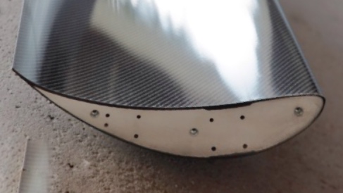
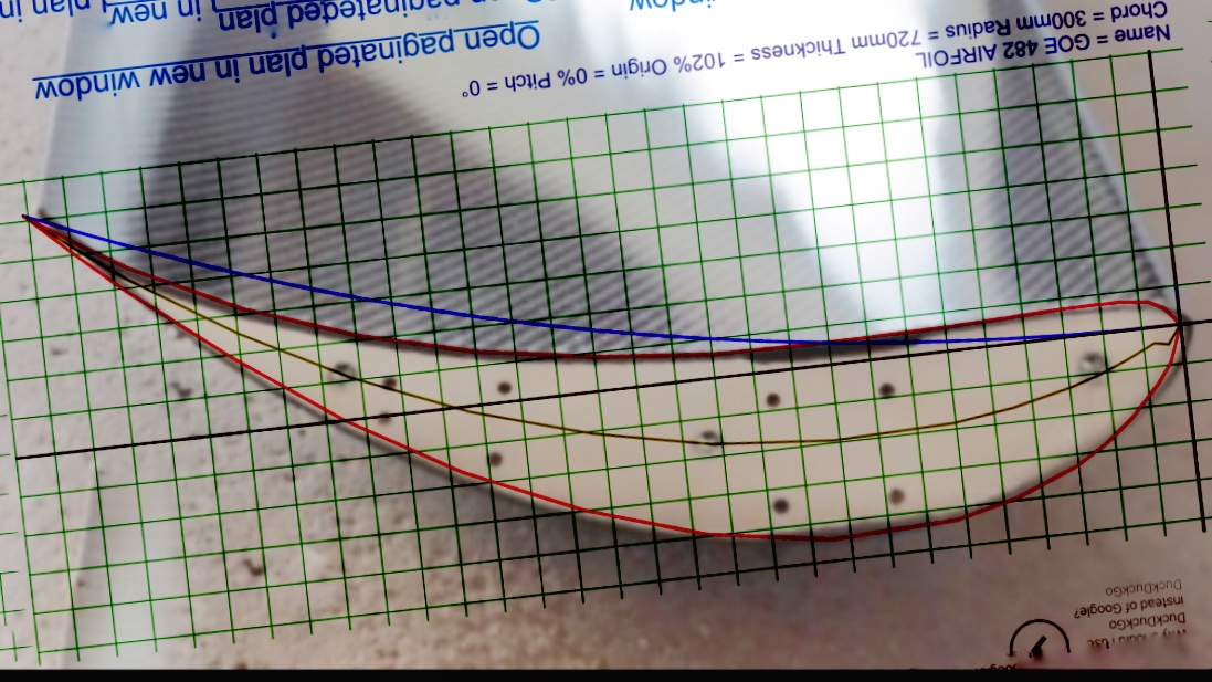
Been whittling away at sourcing a wing to complement the diffuser, and stumbled over an end-on pic of the McBeath SM183 300mm airfoil. If you know of mcbeath you’ll know his wings (and also that the airfoil is a proprietary design). So kindve excited to find s clear pic, I corrected the perspective distortion of the photo a bit in photoshop to achieve my best guess at a relatively flat end-on profile:
12hrs of family holiday lazing by the pool and trawling airfoil catalogues for something comparable... May I present the Göttingen GOE 482 airfoil:
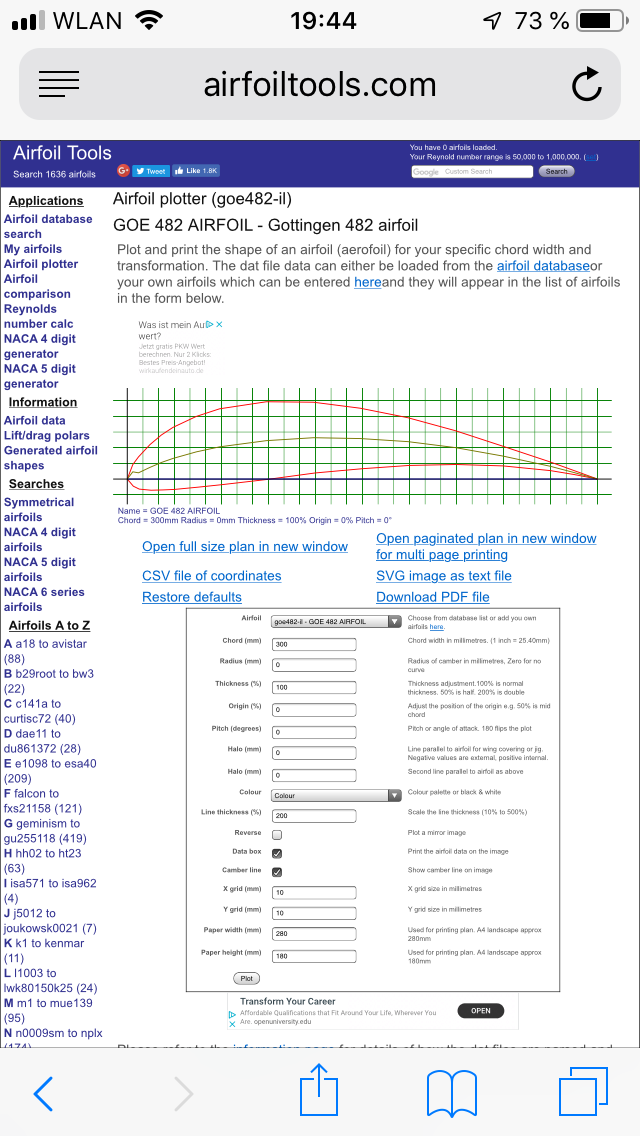
The GOE 482 seems to be currently utilized as a wind turbine airfoil profile, though it’s history goes back to 1921 with its use on a German prototype sailplane the vampyr: https://en.m.wikiped...over_H_1_Vampyr
That said, according to a slightly more modern publication “Proceedings of the 10th International Conference on Rotor Dynamics – 20th Aug 2018†... it still seems to perform its job well:
Details Dat file Parser
(goe482-il) GOE 482 AIRFOIL
Gottingen 482 airfoil
Max thickness 16.5% at 29.6% chord.
Max camber 8.8% at 39.6% chord

I compared the GOE 482 (and a bunch of other similar profiles (list at the end) to the SM183 pic, and despite being close, you can pretty quickly conclude that McBeath has a fuckload more camber than any off-the-shelf profile... so I started to play around with modifying the camber lines of a few known airfoils. Ultimately modification of the camber line (and 2% extra chord width) of the 482 got me this:
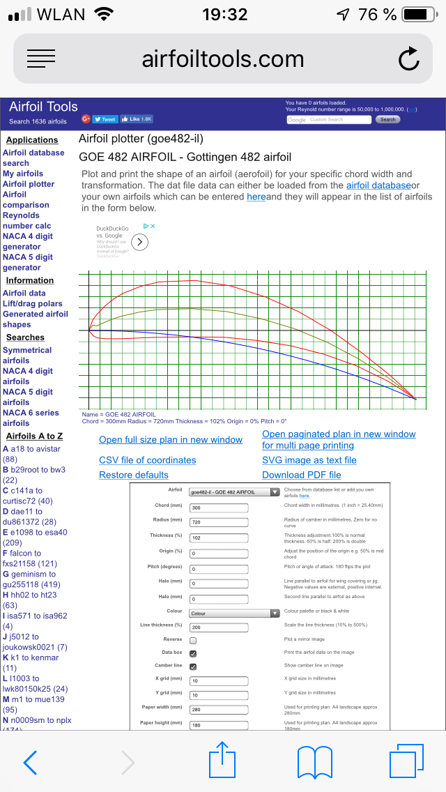
GOE 482 airfoil profiles flipped and aligned for direct comparison (modified camber chord in the foreground, the original slightly ghosted):
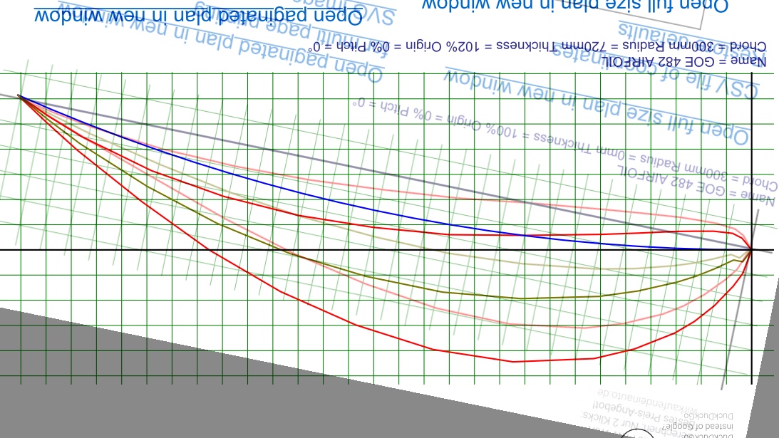
And drumroll... compare my modified GOE 482 with the SM183 airfoil:
Soo... making a wing!?
shortlist of similar "SM183 compatible" airfoils below. none (inc GOE 482) fit without increasing the chord camber, but the general airfoil profile is pretty close taking into account the idiosyncrasies of each design
WORTMANN FX 72-MS-150B AIRFOIL
GOE 242 (MVA PR.2) AIRFOIL (goe242-il)
GOE 523 (525) AIRFOIL
12hrs of family holiday lazing by the pool and trawling airfoil catalogues for something comparable... May I present the Göttingen GOE 482 airfoil:
The GOE 482 seems to be currently utilized as a wind turbine airfoil profile, though it’s history goes back to 1921 with its use on a German prototype sailplane the vampyr: https://en.m.wikiped...over_H_1_Vampyr
That said, according to a slightly more modern publication “Proceedings of the 10th International Conference on Rotor Dynamics – 20th Aug 2018†... it still seems to perform its job well:
Details Dat file Parser
(goe482-il) GOE 482 AIRFOIL
Gottingen 482 airfoil
Max thickness 16.5% at 29.6% chord.
Max camber 8.8% at 39.6% chord
I compared the GOE 482 (and a bunch of other similar profiles (list at the end) to the SM183 pic, and despite being close, you can pretty quickly conclude that McBeath has a fuckload more camber than any off-the-shelf profile... so I started to play around with modifying the camber lines of a few known airfoils. Ultimately modification of the camber line (and 2% extra chord width) of the 482 got me this:
GOE 482 airfoil profiles flipped and aligned for direct comparison (modified camber chord in the foreground, the original slightly ghosted):
And drumroll... compare my modified GOE 482 with the SM183 airfoil:
Soo... making a wing!?
shortlist of similar "SM183 compatible" airfoils below. none (inc GOE 482) fit without increasing the chord camber, but the general airfoil profile is pretty close taking into account the idiosyncrasies of each design
WORTMANN FX 72-MS-150B AIRFOIL
GOE 242 (MVA PR.2) AIRFOIL (goe242-il)
GOE 523 (525) AIRFOIL
#1171
Doctor Ed
-
-
- 1,188 posts
Need to get Out More
- Location:Germany
Posted 11 May 2019 - 10:11 PM
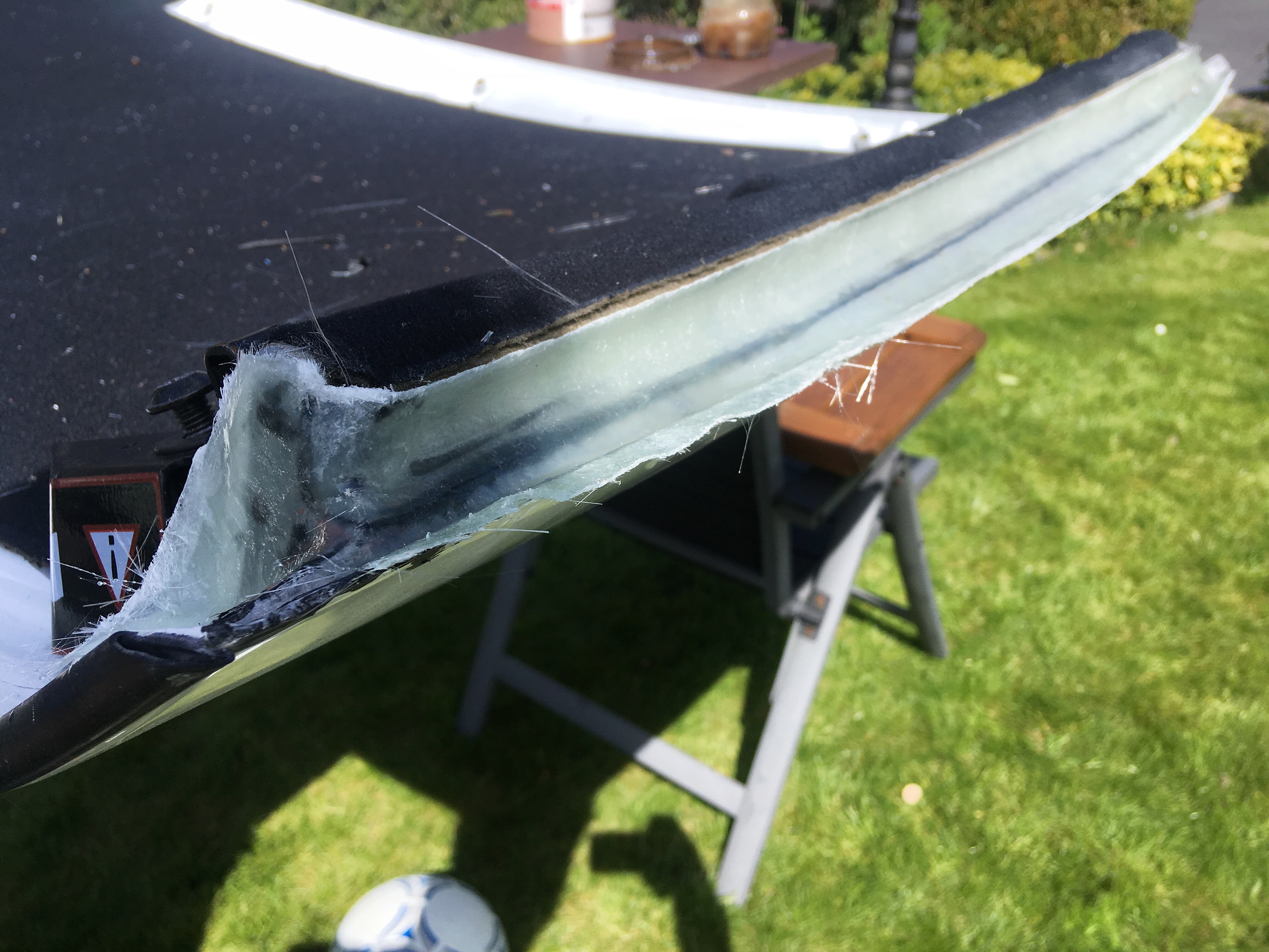
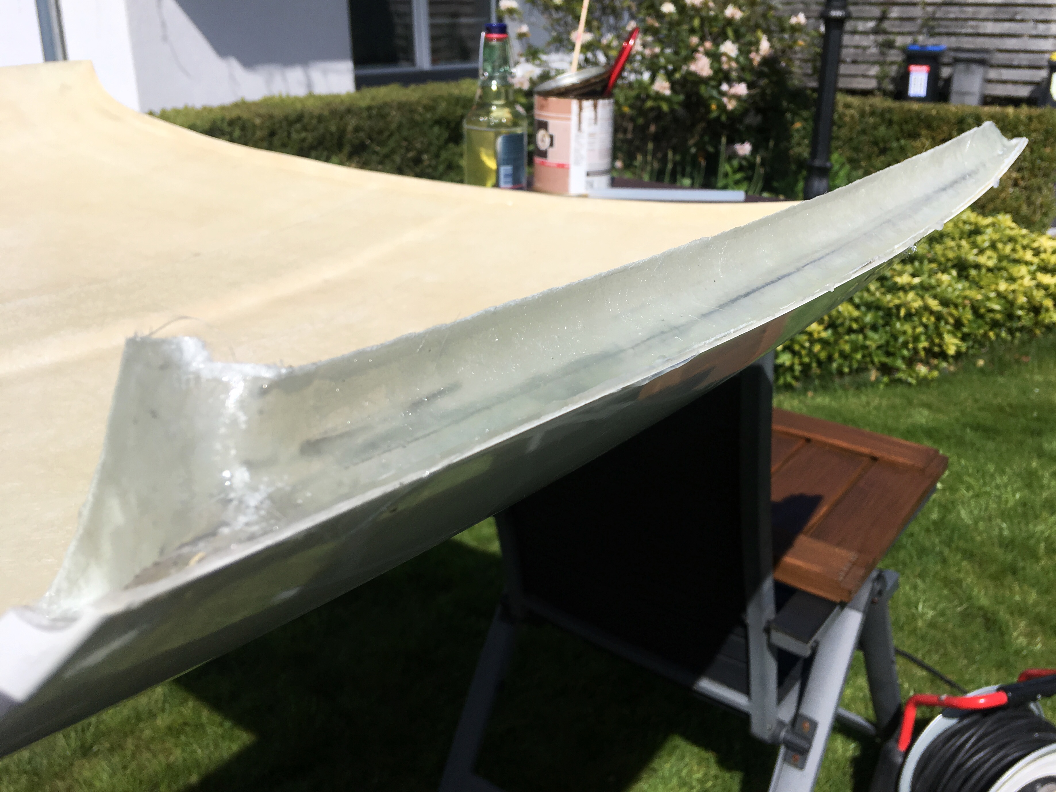
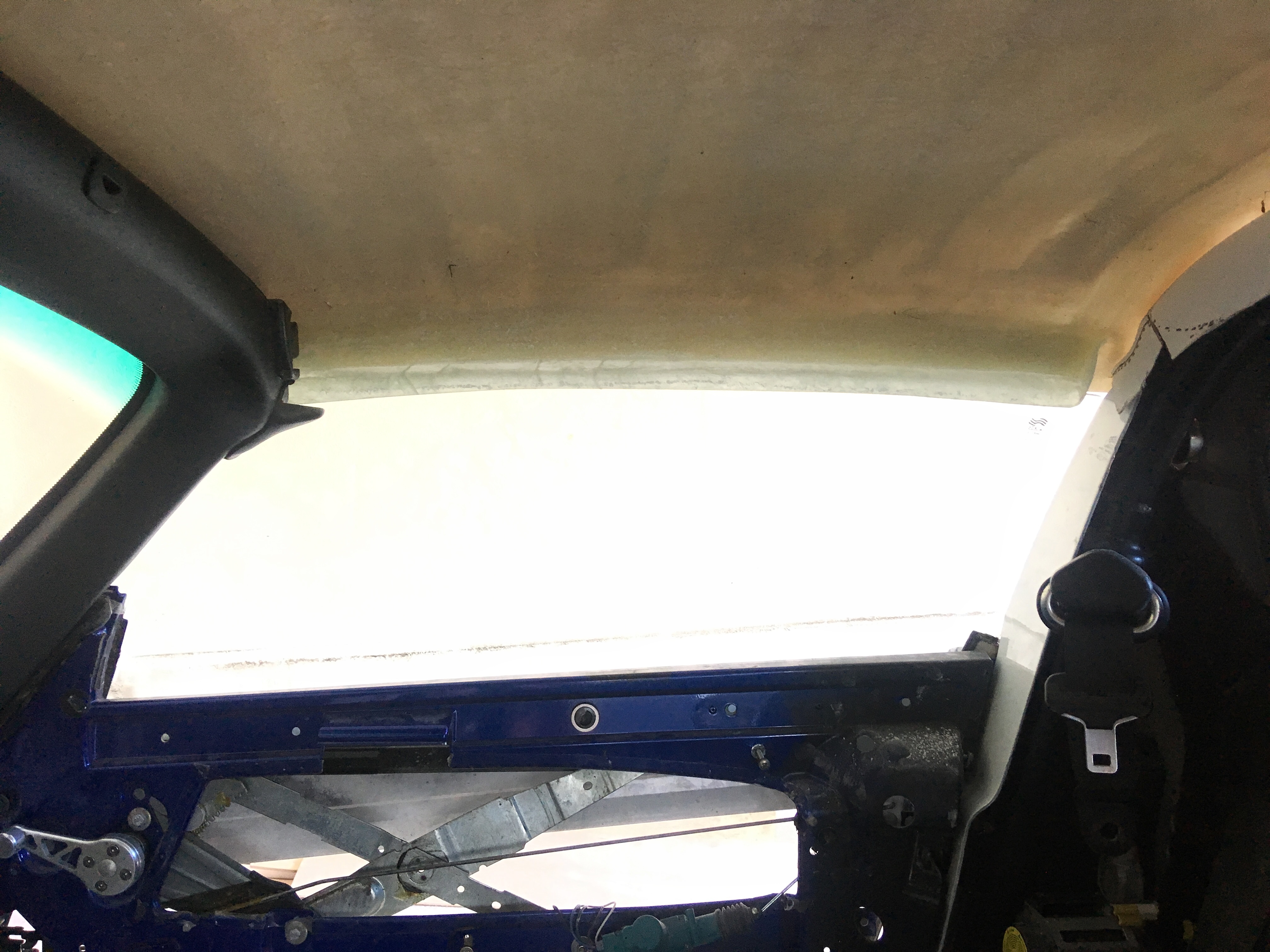
so on the list of sh*t-i-need-but-dont-want-to-do (which is getting longer) has been modifying the single skin elise roof so that it actually has some kind of fastener holding it on, and and fixing up the 'luxuries' of having it close, if not seal. the biggest hurdle of this being getting the fcuking windows to seal. lotus did something weird and has made the roof X compound curve, and the window edge has Y compound curve. the two curves aren't related to each other, there's no straight edges. its a headfuck.
so, pulled the window seals off the OEM roof I've got, sprayed on some release agent, and made a mould of the mounting face of the seal, along with the reference line of the edge of the roof. popped the moulds, then took single skin roof, and hot-glued the moulds to the roof along the roof edge. sprayed some more release agent, and laid up the indorse of the mould blending them into the underside of the roof. wait for things to go off, and pop the hot glue joins and rip the mould off.
only took about 4hrs. was a pleasant saturday on the lawn in the sun with the kids though. need to tidy them up a bit, but they're pretty good i think! now on to fastening the fcuker down
#1172
Doctor Ed
-
-
- 1,188 posts
Need to get Out More
- Location:Germany
Posted 26 May 2019 - 07:47 PM
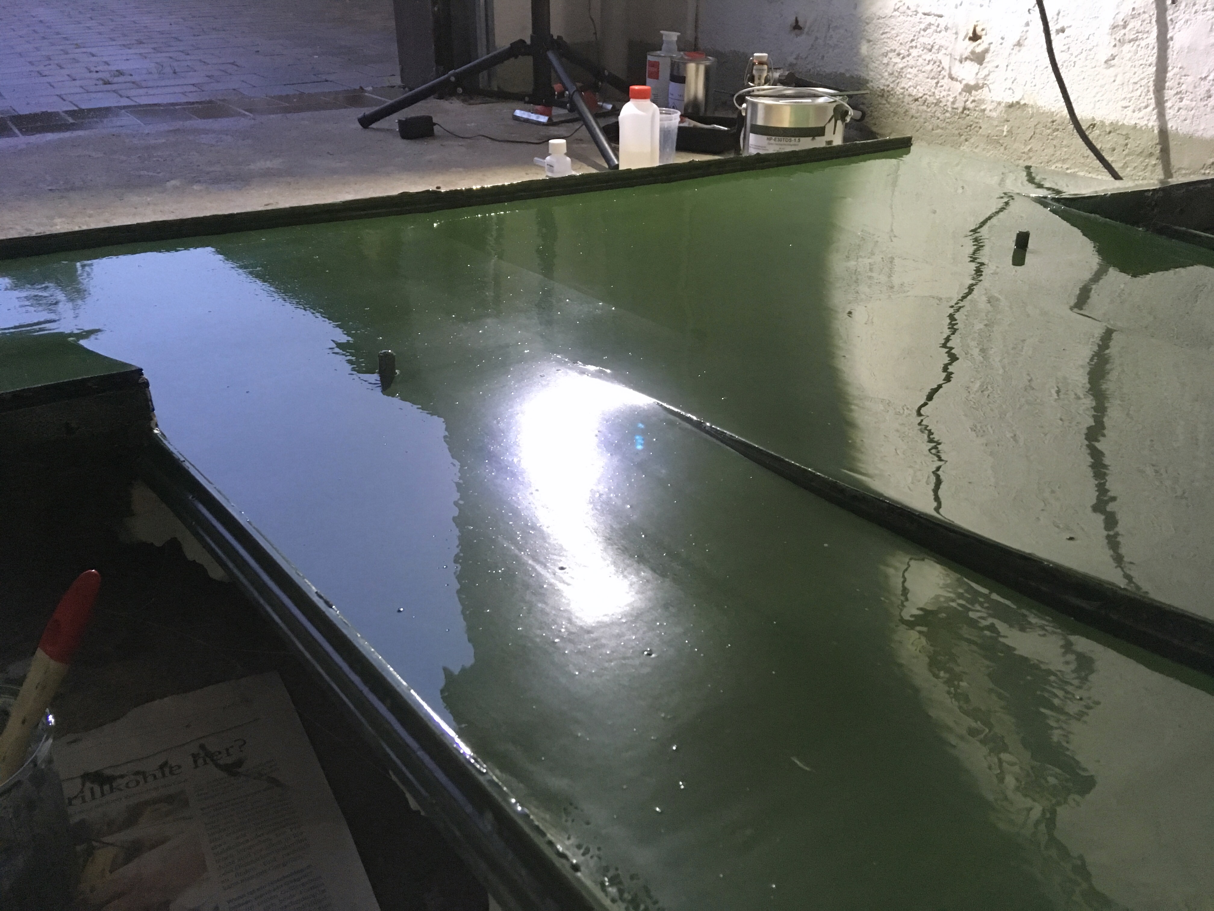
damn near pulled an all-nighter to get this thing to flow coating stage today, but the effort seems to have paid off. it's self levelling (still!) and looking pretty damn glassy (see last pic) but ill still give it a hit with some wet n dry and a reflow with some thinned coat on tuesday (on call tomorrow, so that's out). final cure hardness seems to take 5-7 days, so I need to be a touch patient before finally laying up some carbon. give me lots of time to apply/reapply release agent though.
literally rubbing one out at 2 o'clock in the morning
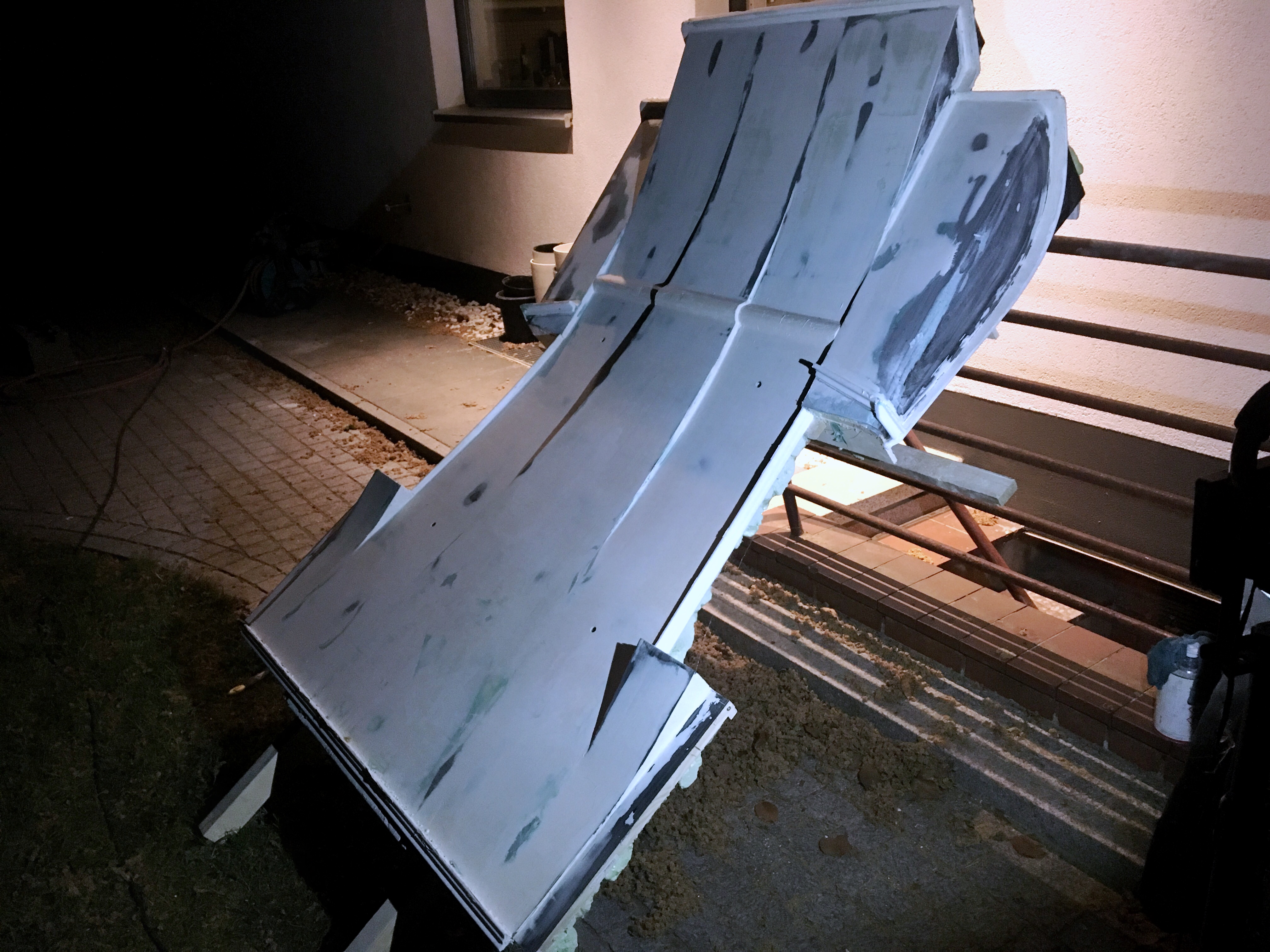
pre flowcoat
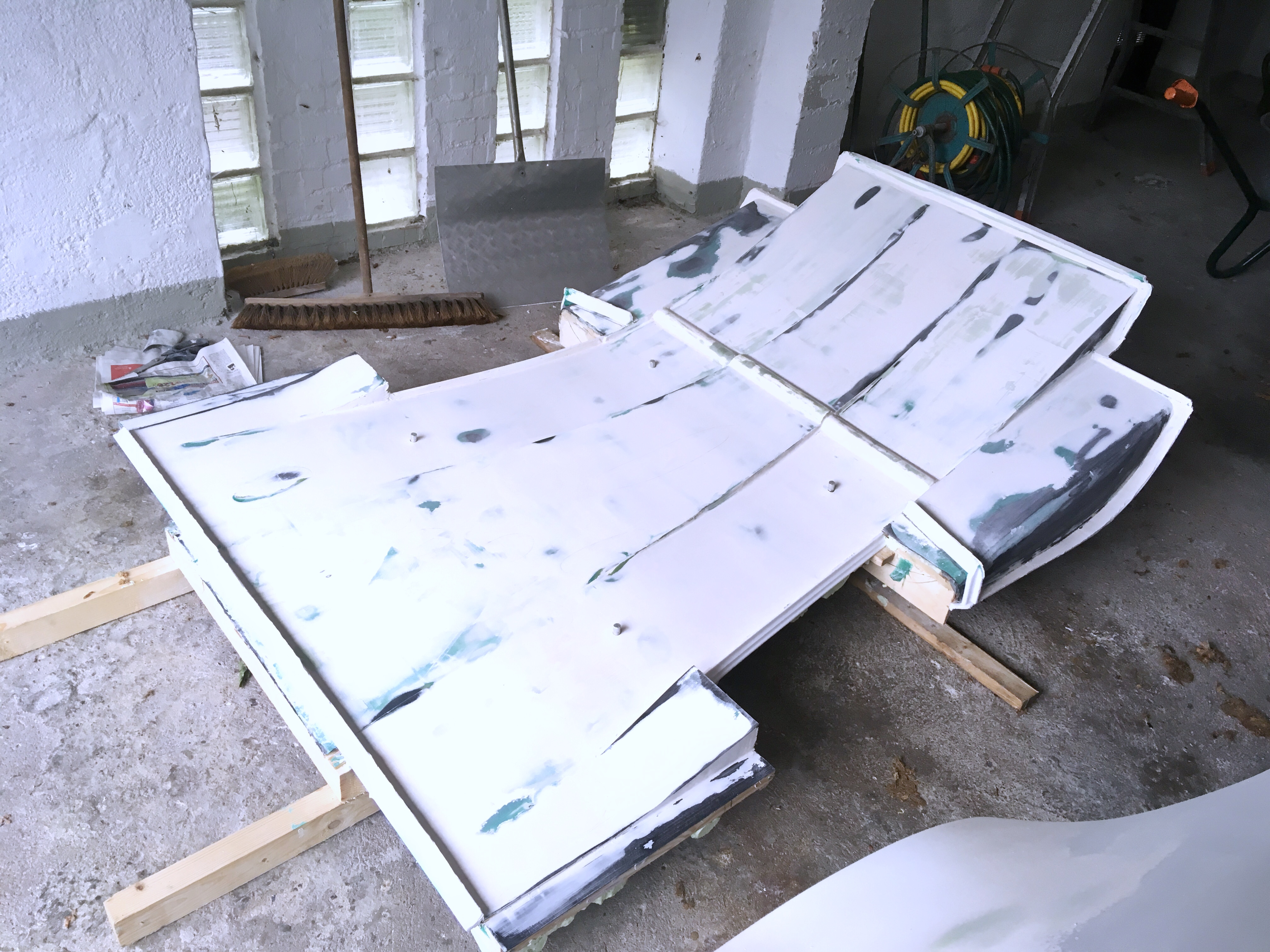
post flowcoat
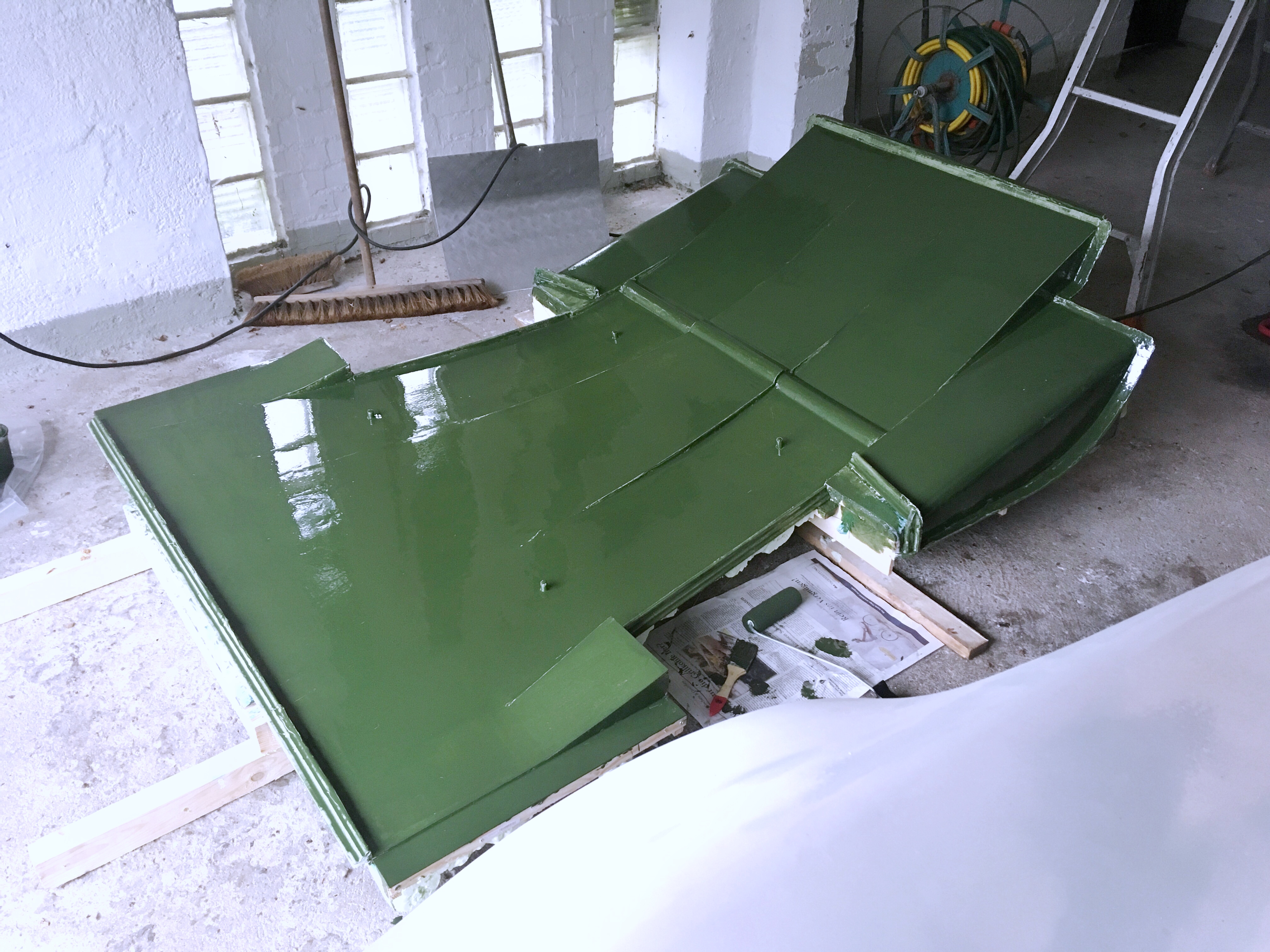
and after a couple of hours how its self levelling is going
literally rubbing one out at 2 o'clock in the morning
pre flowcoat
post flowcoat
and after a couple of hours how its self levelling is going
#1173
Doctor Ed
-
-
- 1,188 posts
Need to get Out More
- Location:Germany
Posted 26 May 2019 - 08:50 PM
ps, assuming my diffuser pops off the mould without destroying it, ill probably try and make a couple. wayyyyy too much work involved just to get one pice out of it! if interested in one, happy to pass one on at basically material cost. won't work with the std clam, so expect to have to get busy with an angle grinder...
#1174
Aerodynamic
-
-
- 1,455 posts
Billy No Mates
Posted 27 May 2019 - 07:45 AM
Very nice. Impressed.
Glass fibre?
Do you have any fins in that diffuser?
If not will you and how do you merge them?
Glass fibre?
Do you have any fins in that diffuser?
If not will you and how do you merge them?
#1175
Doctor Ed
-
-
- 1,188 posts
Need to get Out More
- Location:Germany
Posted 27 May 2019 - 04:35 PM
from bottom to top:
layer 1: 200gsm carbon twill @ 90deg
laver 2: 200gsm carbon twill @ 45deg
layer 3: 225gsm e-glass chopped strand mat
layer 4: 200gsm carbon twill Q 90deg
in high abrasion/impact prone areas ill lay additional strips of 200gsm kevlar twill
in flexy/stressed areas an extra patch of 200gsm carbon twill
at the mounting points im embedding stainless washers
that should make about a 1,5mm thick panel with 40% fiber volume
fins/strakes i cant mould in one liece, and will be added separately after ive recovered from the amount of work its taken to get this far! but generally the strakes will be made separately (same carbon/epoxy mix), and will be simply bonded on with some carbon specific methyl methacrylate structural adhesive
#1176
paul_mck
-

-
- 284 posts
Super Member
- Location:NI
Posted 27 May 2019 - 07:35 PM
just landed into this thread (new to forum). All I can say is wow! Unreal amount of work, and loving the skill involved.
#1177
Bakazan
-

-
- 234 posts
Member
- Gender:Male
Posted 28 May 2019 - 07:13 AM
from bottom to top:
layer 1: 200gsm carbon twill @ 90deg
laver 2: 200gsm carbon twill @ 45deg
layer 3: 225gsm e-glass chopped strand mat
layer 4: 200gsm carbon twill Q 90deg
in high abrasion/impact prone areas ill lay additional strips of 200gsm kevlar twill
in flexy/stressed areas an extra patch of 200gsm carbon twill
at the mounting points im embedding stainless washers
that should make about a 1,5mm thick panel with 40% fiber volume
fins/strakes i cant mould in one liece, and will be added separately after ive recovered from the amount of work its taken to get this far! but generally the strakes will be made separately (same carbon/epoxy mix), and will be simply bonded on with some carbon specific methyl methacrylate structural adhesive
What's the thinking in including a layer of glass?
#1178
FLD
-

-
- 13,717 posts
WANNABE MY LOVER
- Gender:Male
- Location:Near nantwich
- Interests:Tugging my todger.
Posted 28 May 2019 - 10:30 AM
In any laminate its the outer layers that do the work. using a glass core is a way of adding thickness without costing a fortune. Might be this?
#1179
Doctor Ed
-
-
- 1,188 posts
Need to get Out More
- Location:Germany
Posted 28 May 2019 - 04:23 PM
pretty much that ^^^^
plus the chopped strand is polyaxially quite strong stuff in itself. adds another dimension of stability to the otherwise relitivly square fibers of the CF. proper core material would also be good, but thickness would then start to become a problem
plus the chopped strand is polyaxially quite strong stuff in itself. adds another dimension of stability to the otherwise relitivly square fibers of the CF. proper core material would also be good, but thickness would then start to become a problem
#1180
Doctor Ed
-
-
- 1,188 posts
Need to get Out More
- Location:Germany
Posted 30 May 2019 - 10:25 AM
Apparently I forgot to order release agent, and it’s getting laid up today, no matter what! So frantic dig around the house to find what I’ve got on hand (public holiday, nothing open) and a bit of googling later...
Lo and behold kiwi neutral shoe polish is a no frills Carnauba Wax in naphtha. So midnight flames, an old t shirt, and elbow grease...
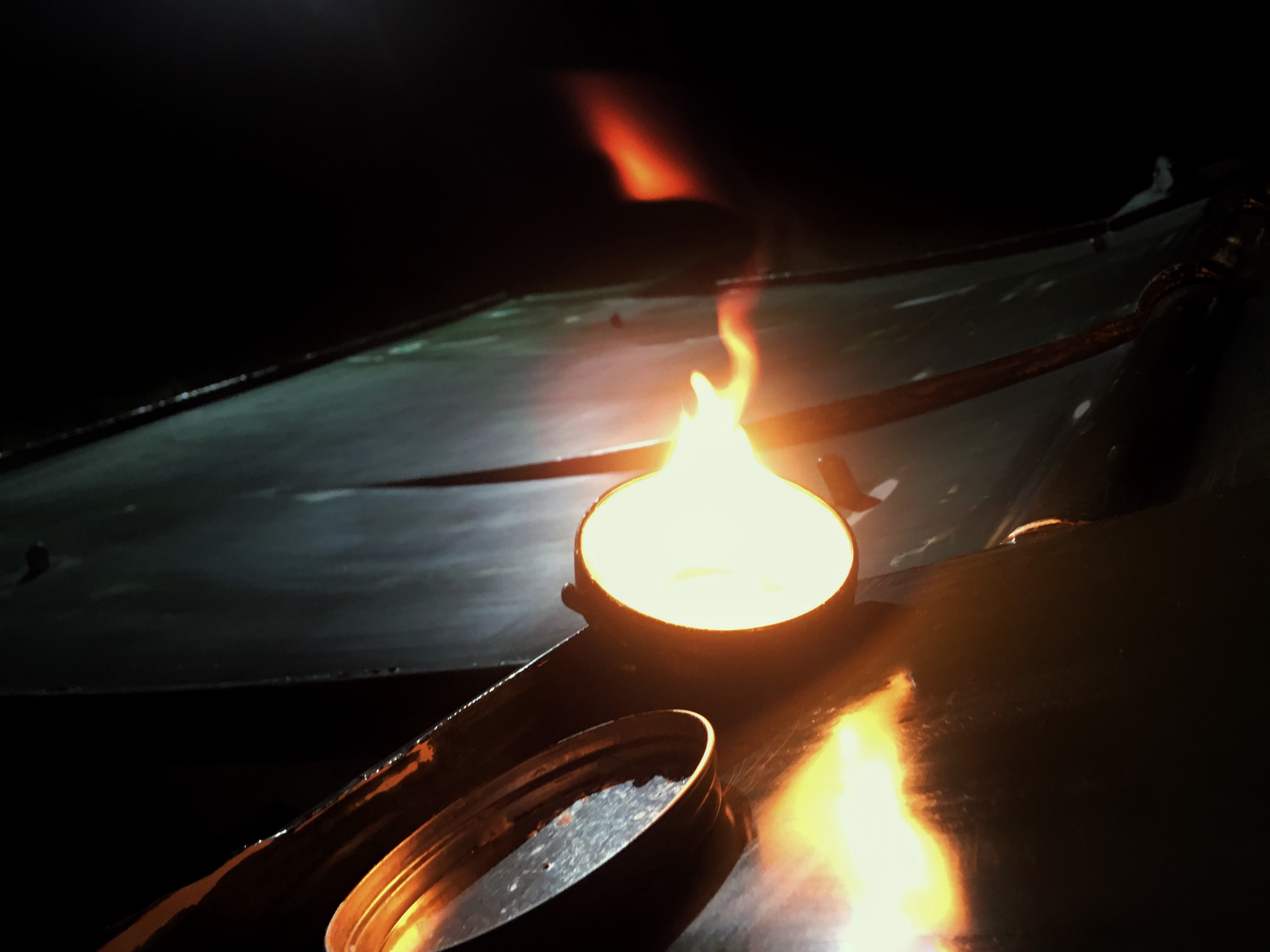
Lo and behold kiwi neutral shoe polish is a no frills Carnauba Wax in naphtha. So midnight flames, an old t shirt, and elbow grease...


0 user(s) are reading this topic
0 members, 0 guests, 0 anonymous users

