P1635 And 1271 With No Throttle Response
#21

Posted 08 January 2017 - 02:50 PM
#22

Posted 08 January 2017 - 07:52 PM
NO!!! Don't solder it. Worst case scenario swap the plugs out for some decent deutsch ones. Expensive but they work well.
#23

Posted 08 January 2017 - 08:43 PM
Available from RS componentsNO!!! Don't solder it. Worst case scenario swap the plugs out for some decent deutsch ones. Expensive but they work well.
#24

Posted 09 January 2017 - 12:53 PM
#25

Posted 09 January 2017 - 01:45 PM
these should be the correct plugs
http://www.polevolt....nfo_ESC13F.html
http://www.polevolt....nfo_ESC13M.html
#26

Posted 09 January 2017 - 05:47 PM
Thanks vocky, I'll get some of those ordered. Just thought, does anybody near me have an op-com they'd be willing to let me borrow?these should be the correct plugs
#27

Posted 09 January 2017 - 09:09 PM
#28

Posted 09 January 2017 - 09:51 PM
http://www.zincprote...ng diagrams.pdf Looking at diagrams 10 and 11 on here. Sorry meant APP sensorTerminals can be had at vehicle wiring products. I thought the blue plug was tps side and black plug was body side? Sent from my iPhone using Tapatalk
#29

Posted 10 January 2017 - 12:05 PM
I have 2 redundant throttle body's - both in full working order you can have one for the price of a Yorkshire ale plust p+p if you want.
Also have you checked that one of the connectors hasn't riggled back slightly free of the throttle body connector - check the back of the plug you will see the round rubber water insulation sock further back on one of the wires compared with the others.
#30

Posted 10 January 2017 - 12:10 PM
x21 = J1 ecu
x22 = J2 ecu
X2 - blue plug
pin 1 = bn/pk (pin 87 of relay K18, +12v for fuel injectors)
pin 2 = wh/bk (instrument - rev counter) + (start relay K24 pin 9)
pin 3 = brn/red (post cat lambda)
pin 4 = blk/red (post cat lambda)
pin 5 = gn (+12v FuseBox 7, switched)
pin 6 = blk/red (post cat lambda)
pin 7 = brn/pink (post cat lambda)
pin 8 = wh/vt (+12v for relay coil, pin 85 - fuel pump relay K16)
pin 9 = gn/bu (instrument - coolant temp gauge [pulsed signal from ecu])
pin 10 = n/c
pin 11 = n/c
pin 12 = gn/pk (0v for relay coil, pin 85 - ECU relay K18)
pin 13 = bu/gy (0v for relay coil, pin 85 - radiator fan relay)
X3 - black plug
pin 1 = ye (throttle pedal)
pin 2 = gn (throttle pedal)
pin 3 = bu (throttle pedal)
pin 4 = bk (throttle pedal)
pin 5 = wh (throttle pedal)
pin 6 = bn (throttle pedal)
pin 7 = n/c
pin 8 = bn/bu (instrument - oil pressure light)
pin 9 = wh/ye (immobiliser)
pin 10 = bn/bu (instrument - engine management light)
pin 11 = ye/gy (ABS pin 3 - speed signal for engine ecu)
pin 12 = n/c
pin 13 = vt [+12v FuseBox 8, permanent]
#31

Posted 10 January 2017 - 12:47 PM
Thank you for the offer, I've got 2 TBs here, tried both and has made no difference so I think I can rule the throttle body out. Also the codes I'm getting relate to the accelerator pedal, loom of doom and X21 ECU connector side of the wiring. I expect the problem lies here. I've tried exposing the wires just back from the TB connector and probing the plug to check for continuity with continuity on all terminals. From what I understand from the wiring diagrams the chain goes: Accelerator pedal - Loom of Doom (X3 black) - ECU LH connector (X21) - ECU - ECU RH connector (X22) - Throttle bodyI have 2 redundant throttle body's - both in full working order you can have one for the price of a Yorkshire ale plust p+p if you want. Also have you checked that one of the connectors hasn't riggled back slightly free of the throttle body connector - check the back of the plug you will see the round rubber water insulation sock further back on one of the wires compared with the others.
#32

Posted 10 January 2017 - 12:50 PM
Thank you for the offer, I've got 2 TBs here, tried both and has made no difference so I think I can rule the throttle body out. Also the codes I'm getting relate to the accelerator pedal, loom of doom and X21 ECU connector side of the wiring. I expect the problem lies here. I've tried exposing the wires just back from the TB connector and probing the plug to check for continuity with continuity on all terminals. From what I understand from the wiring diagrams the chain goes: Accelerator pedal - Loom of Doom (X3 black) - ECU LH connector (X21) - ECU - ECU RH connector (X22) - Throttle bodyI have 2 redundant throttle body's - both in full working order you can have one for the price of a Yorkshire ale plust p+p if you want. Also have you checked that one of the connectors hasn't riggled back slightly free of the throttle body connector - check the back of the plug you will see the round rubber water insulation sock further back on one of the wires compared with the others.
No problem offer is there.
Have you considerd it may be the pedal fly by wire bit.
#33

Posted 10 January 2017 - 12:55 PM
This is what I thought initially, trying to source a replacement I can just plug in and test. I've ordered an OPCOM so I should be able to read the values registered by the pedal in the meantime.No problem offer is there. Have you considerd it may be the pedal fly by wire bit.
#34

Posted 10 January 2017 - 01:17 PM
#35

Posted 10 January 2017 - 01:26 PM
Simple enough circuit it's just two variable resistors like on a scaelectric trigger. Usually works in the range 0.50v to 4.50v the 0.50v either end is for the ecu to recognise when they are faulty. Perhaps Vocky knows which two wires provide the signal back to ecu ? Sent from my SM-G903F using Tapatalk
Actually taken a look at the diagram - ref Vockys post above with pin no's it looks like pin 3 and pin 6 connector X3
using a multimeter set to volts read the voltage on these wires (black to chassis earth red to each wire in turn)
should go from 0.50 to 4.50 v
One may also go from 4.50 to 0.50 not tested one of these on this car but done plenty of others.
#36

Posted 10 January 2017 - 01:37 PM
Just ran your codes through my database - P1271 is APP signal correlation error.
In English the ecu compares the 2 signals (voltages) coming from the APP and one is potentially wrong.
There are two for safety reasons, if there were one only and it stuck at full throttle then the ecu would take it as gospel that you want flat out. By having two it has something to compare against, ie one flat out the other part throttle means a pedal signal fault.
So to diagnose you just need to find out which signal is the faulty one then go from there it will be on one of the two wires mentioned above.
#37

Posted 10 January 2017 - 01:40 PM
One other quick check.
Stamp hard up and down repeatedly (5 times ish) on the throttle pedal it may clear the fault if its the pedal - if the fault goes away order a pedal and chill out
Basically it will clean the pedal internal components long enough to clear the fault (temporarily though)
#38

Posted 10 January 2017 - 01:57 PM
Actually taken a look at the diagram - ref Vockys post above with pin no's it looks like pin 3 and pin 6 connector X3 using a multimeter set to volts read the voltage on these wires (black to chassis earth red to each wire in turn) should go from 0.50 to 4.50 v One may also go from 4.50 to 0.50 not tested one of these on this car but done plenty of others.Simple enough circuit it's just two variable resistors like on a scaelectric trigger. Usually works in the range 0.50v to 4.50v the 0.50v either end is for the ecu to recognise when they are faulty. Perhaps Vocky knows which two wires provide the signal back to ecu ? Sent from my SM-G903F using Tapatalk
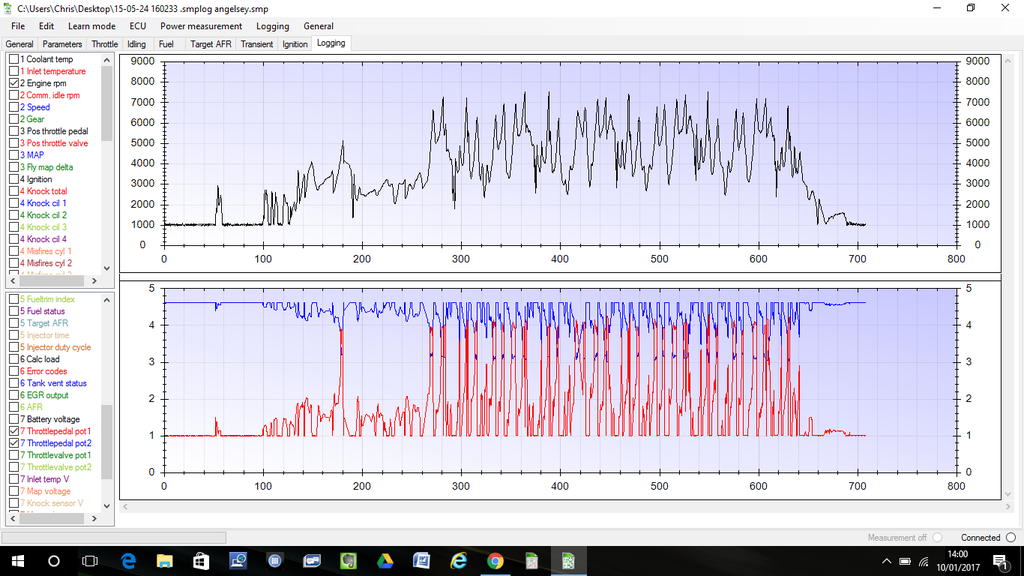
There are two throttle pots work as opposites You are able to log all of these using the loggging function which makes it great for these types of faultshave you checked your ecu pins ? it has somthing to do with the 2 pot from the throttle not working in harmony
#40

Posted 10 January 2017 - 02:10 PM
another good reason to to use obdtuner to find these faults
i think the code is triggered when the ecu does not get what it expects to see from each of the two pots
1 user(s) are reading this topic
0 members, 1 guests, 0 anonymous users


