This is remarkably similar to what I had a few years back. Had full continuity but eml hell. It was just weak terminals giving sporadic loss of signal due to vibrations. Check for corrosion on the ecu pins then look to swap the terminals. Pester me and I'll dig out the ref number.
Sent from my iPhone using Tapatalk

P1635 And 1271 With No Throttle Response
Started by
AlexHillTVR
, Jan 07 2017 04:23 PM
69 replies to this topic
#41

FLD
-

-

- 13,717 posts
WANNABE MY LOVER
- Gender:Male
- Location:Near nantwich
- Interests:Tugging my todger.
Posted 10 January 2017 - 03:37 PM
#42
AlexHillTVR
-
-
- 242 posts
Member
- Gender:Male
- Location:Surrey
- Interests:Running, Mountain Biking, Photography, Guitar
Posted 10 January 2017 - 05:21 PM
Thanks guys, so much useful information on here. I'll be home in 5 mins and will crack on with the multimeter again!
#43
FLD
-
-
- 13,717 posts
WANNABE MY LOVER
- Gender:Male
- Location:Near nantwich
- Interests:Tugging my todger.
Posted 10 January 2017 - 06:13 PM
Don't have the reference no for the terminals any more but I do have a few spare. Not enough to replace them all though  Sent from my iPhone using Tapatalk
Sent from my iPhone using Tapatalk
#44
AlexHillTVR
-
-
- 242 posts
Member
- Gender:Male
- Location:Surrey
- Interests:Running, Mountain Biking, Photography, Guitar
Posted 10 January 2017 - 06:55 PM
https://youtu.be/QSe3PkWoACs
Here's a video of the problem for reference, made some progress that I'll detail below!
#45
AlexHillTVR
-
-
- 242 posts
Member
- Gender:Male
- Location:Surrey
- Interests:Running, Mountain Biking, Photography, Guitar
Posted 10 January 2017 - 08:13 PM
So, with a small amount of wire exposed on the wires either side of the loom of doom connectors, I decided to do some probing with my very basic multimeter tonight. Firstly checked again for continuity across the loom of doom. All fine, coming back with 0.00V.
Then I moved on to reading some voltages with the ignition turned on using the zincprotest VX220 wiring diagram for reference.
5V to gnd, ECU side of LOD
Pins 1 and 5 = 4.98V
Pins 2 and 4 = 4.97V
APP signal to gnd, ECU side of LOD (no pedal input)
Pins 6 and 5, APP 1 = -0.5 to -0.7V fluctuating randomly (multimeter tends to do this if there's a break in the circuit)
Pins 3 and 4, APP 2 = 0.97V
APP signal to gnd, pedal side of LOD
Pins 6 and 5, APP 1 = -0.5 to -0.7V fluctuating randomly (multimeter tends to do this if there's a break in the circuit)
Pins 3 and 4, APP 2 = 0.97V
The same reading either side of the loom of doom make me think it's not the problem now. So the problem is most likely, in my opinion with the pedal. Tried stamping on it several times but made no difference annoyingly. Joe is very kindly sending a replacement so will be able to rule that out.
#46
AlexHillTVR
-
-
- 242 posts
Member
- Gender:Male
- Location:Surrey
- Interests:Running, Mountain Biking, Photography, Guitar
Posted 10 January 2017 - 08:14 PM
Excuse the 0.00V bit, I meant ohms.
#47
CHILL Gone DUTCH
-
-
- 13,727 posts
I ADMIT BATMAN THINKS HE IS QUICKER THAN ME
- Gender:Male
- Location:UK
Posted 10 January 2017 - 08:17 PM
can you measure the voltages at the pedal
#48
FLD
-
-
- 13,717 posts
WANNABE MY LOVER
- Gender:Male
- Location:Near nantwich
- Interests:Tugging my todger.
Posted 10 January 2017 - 08:28 PM
OPCOM has a throttle test function where you can watch the pedal signals.
#49
AlexHillTVR
-
-
- 242 posts
Member
- Gender:Male
- Location:Surrey
- Interests:Running, Mountain Biking, Photography, Guitar
Posted 10 January 2017 - 08:54 PM
I'd like to, doesn't look like I can back-probe the connector? Can you advise a way to do it? Basically the ECU runs two lines of 5V and gnd to the pedal and the pedal has two potentiometers which send back the voltage from the pedal is what I have learned. The ECU then looks at these two voltages and goes either "they look right" or "Oh sh*t! They don't correspond so I'm gonna cut the voltage to the throttle body. Also thanks FLD, my OPCOM comes tomorrow so I'll make sure I use that function.can you measure the voltages at the pedal
#50
CHILL Gone DUTCH
-
-
- 13,727 posts
I ADMIT BATMAN THINKS HE IS QUICKER THAN ME
- Gender:Male
- Location:UK
Posted 10 January 2017 - 08:57 PM
opcom will only read the return voltage at the ecu
you need to no what the voltage are at the pedal so you know if its the return wires or the potentiometers or even the feed wires to the pedal
ie
make sure the return voltages at the pedal are the same at the plugs and ecu
Edited by CHILL Gone DUTCH, 10 January 2017 - 09:06 PM.
#51
Exmantaa
-

-
- 3,982 posts
Scary Internerd
- Gender:Male
Posted 10 January 2017 - 09:17 PM
I'd like to, doesn't look like I can back-probe the connector? Can you advise a way to do it? Basically the ECU runs two lines of 5V and gnd to the pedal and the pedal has two potentiometers which send back the voltage from the pedal is what I have learned. The ECU then looks at these two voltages and goes either "they look right" or "Oh sh*t! They don't correspond so I'm gonna cut the voltage to the throttle body. Also thanks FLD, my OPCOM comes tomorrow so I'll make sure I use that function.can you measure the voltages at the pedal
As said; the throttle pedal has 2 independent potmeters; each with it's own reference ecu ground and reference +5.0v. 1 potmeter goes up while the other voltage goes down with throttle input.
So you have 6 wires; 2 x +5.0v, 2x ecu ground and 2 x potmeter signal:
X3 - black plug (have to check which pin does what, but think 3 & 6 are pot signals)
pin 1 = ye (throttle pedal) pin 2 = gn (throttle pedal) pin 3 = bu (throttle pedal) pin 4 = bk (throttle pedal) pin 5 = wh (throttle pedal) pin 6 = bn (throttle pedal)
https://www.speedste...e Z22SE - 1.pdf
With ignition on (don't press the pedal while switching on), my pedal voltages read:
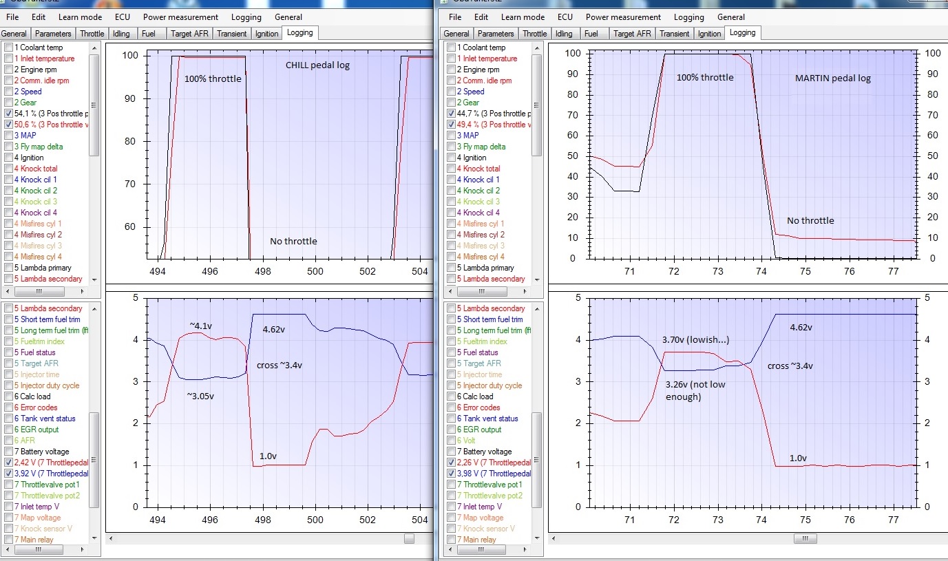
No pedal input => signal A = ~1.0v, signal B = ~4.6v
WOT pedal => signal A = ~4.1v, signal B = ~3.1v
Edit;
So measure with your multimeter grounded to the ecu outside metal and ignition on:
- Search for the 2x 5.0v reference voltage pins
- Search for the 2x reference ecu ground pins. (check there is no resistance to ecu ground)
- Measure both pedal signal pin voltages; both with no throttle input and WOT pedal input. These should measure something similar to my voltages.
Edited by Exmantaa, 10 January 2017 - 09:22 PM.
#52
Exmantaa
-
-
- 3,982 posts
Scary Internerd
- Gender:Male
Posted 10 January 2017 - 09:40 PM
from my old notes:
X3 connector (black 13 pin) Pin #
1 Pedal sensor 2 Low ref (ecu ground) 2 Pedal sensor 1 5V ref 3 Pedal sensor 1 Signal 1 4 Pedal sensor 1 Low ref (ecu ground) 5 Pedal sensor 2 5V ref 6 Pedal sensor 2 Signal 2
#53
AlexHillTVR
-
-
- 242 posts
Member
- Gender:Male
- Location:Surrey
- Interests:Running, Mountain Biking, Photography, Guitar
Posted 10 January 2017 - 09:41 PM
Cheers for the clarification there. Only measured with no throttle input, got the right reading for APP sensor 2 but APP sensor 1 seemed to show something completely wrong or an open circuit. Need to do a test with a friend pressing the gas pedal to WOT but I'm thinking APP sensor 1 pot is shaggedAs said; the throttle pedal has 2 independent potmeters; each with it's own reference ecu ground and reference +5.0v. 1 potmeter goes up while the other voltage goes down with throttle input. So you have 6 wires; 2 x +5.0v, 2x ecu ground and 2 x potmeter signal: X3 - black plug (have to check which pin does what, but think 3 & 6 are pot signals) pin 1 = ye (throttle pedal) pin 2 = gn (throttle pedal) pin 3 = bu (throttle pedal) pin 4 = bk (throttle pedal) pin 5 = wh (throttle pedal) pin 6 = bn (throttle pedal) https://www.speedste...e Z22SE - 1.pdf With ignition on (don't press the pedal while switching on), my pedal voltages read: No pedal input => signal A = ~1.0v, signal B = ~4.6v WOT pedal => signal A = ~4.1v, signal B = ~3.1v Edit; So measure with your multimeter grounded to the ecu outside metal and ignition on: - Search for the 2x 5.0v reference voltage pins - Search for the 2x reference ecu ground pins. (check there is no resistance to ecu ground) - Measure both pedal signal pin voltages; both with no throttle input and WOT pedal input. These should measure something similar to my voltages.
I'd like to, doesn't look like I can back-probe the connector? Can you advise a way to do it? Basically the ECU runs two lines of 5V and gnd to the pedal and the pedal has two potentiometers which send back the voltage from the pedal is what I have learned. The ECU then looks at these two voltages and goes either "they look right" or "Oh sh*t! They don't correspond so I'm gonna cut the voltage to the throttle body. Also thanks FLD, my OPCOM comes tomorrow so I'll make sure I use that function.can you measure the voltages at the pedal
#54
Exmantaa
-
-
- 3,982 posts
Scary Internerd
- Gender:Male
Posted 10 January 2017 - 09:45 PM
If something measures wonky there; look upstream towards the pedal.
Could be faulty pedal or Pedal connector. There were cases reported of a chafed wiring loom to the gearchange mechanism inside the centre console...
Ow, bit hard to do, but while measuring with moving pedal input; check for a gradual change in voltages.
Edited by Exmantaa, 10 January 2017 - 09:48 PM.
#55
AlexHillTVR
-
-
- 242 posts
Member
- Gender:Male
- Location:Surrey
- Interests:Running, Mountain Biking, Photography, Guitar
Posted 10 January 2017 - 09:50 PM
Good point, if it's not the pedal or connector I reckon I'll be somewhere between the pedal connector and loom of doom, which is the wiring that runs up the centre of the cabin under the centre console and that passenger and driver foot space "divider"?If something measures wonky there; look upstream towards the pedal. Could be faulty pedal or Pedal connector. There were cases reported of a chafed wiring loom to the gearchange mechanism inside the centre console... Ow, bit hard to do, but while measuring with moving pedal input; check for a gradual change in voltages.
#56
Exmantaa
-
-
- 3,982 posts
Scary Internerd
- Gender:Male
Posted 10 January 2017 - 09:55 PM
Yep; centre console is suspect then, as the wiring loom is ty-wrapped to metal and very close to moving parts. Inside the footspace divider the loom is not so vulnerable.
#57
Exmantaa
-
-
- 3,982 posts
Scary Internerd
- Gender:Male
Posted 10 January 2017 - 10:00 PM
This pic shows the 2 pedal voltages going up and down. (look to the good left graph, as MartinS had some "throttle issues" back then...)
Edited by Exmantaa, 10 January 2017 - 10:01 PM.
#58
FLD
-
-
- 13,717 posts
WANNABE MY LOVER
- Gender:Male
- Location:Near nantwich
- Interests:Tugging my todger.
Posted 18 January 2017 - 12:48 PM
Any progress with this, are you all fixed?
Sent from my iPhone using Tapatalk
#59
markanswrth
-

-
- 90 posts
Member
- Location:Oxfordshire
Posted 18 January 2017 - 01:51 PM
This thread is very useful thanks!
I have what appears to be an identical problem. Planning to have a good check of all the connectors and loom over the next few weeks!
#60
AlexHillTVR
-
-
- 242 posts
Member
- Gender:Male
- Location:Surrey
- Interests:Running, Mountain Biking, Photography, Guitar
Posted 19 January 2017 - 12:55 PM
Hi guys,
Swapped the accelerator pedal and got throttle control back. Still throwing up an intermittent P1635 and P0405 which cut the throttle. After logging live data with OpCom it appears that the EGR position command dies just before the ECU goes into limp home mode.
Seeing as the EGR is one of the components that is sent the 5V reference signal (P1635) and P0405 relates directly to the EGR pin A, I'd suspect my EGR cheater is internally knackered or the wiring is duff. Got a new one coming so will update if this solves the problem then the beast is going up for sale!


0 user(s) are reading this topic
0 members, 0 guests, 0 anonymous users

