Theres no way I'm taking teh clam off, dont have the skills or time. Will do something in situ.
I have had the 4-1 manifold for 2000 miles now, so any damage is immediate.
Martin s
ps Pictures sent

Heat Shield Melting
Started by
MartinS
, Jun 02 2008 07:57 AM
74 replies to this topic
#21

MartinS
-
-

- 5,173 posts
I only bought it for one summer. 14 years ago and now its gone&#
- Gender:Male
- Location:Rustington, West Sussex
-
Interests:Track days
Pubs
Sausages
Posted 02 June 2008 - 02:35 PM
#22
MartinS
-
-
- 5,173 posts
I only bought it for one summer. 14 years ago and now its gone&#
- Gender:Male
- Location:Rustington, West Sussex
-
Interests:Track days
Pubs
Sausages
Posted 02 June 2008 - 03:01 PM
I meant, any damage 'isnt' immediate!
If I was to use the rigid nimbus heat shielding could it be mounted away from the surface of the back of the boot via maybe a couple of alluminim bars. If so, if they were bolted through the boot wall, would the heat be transferred through those bolts into the fibreglass?
If it were just glued on the backwall, is it safe to use any old sort of glue, glue for nails etc??
Martin s
Sorry for so many questions, just not particularly technical.
#23
techieboy
-

-

- 22,914 posts
Supercharger of Doom
- Gender:Male
- Location:Bedford
Posted 02 June 2008 - 03:06 PM
Here's a pic of what Martin is dealing with. The heatshield looks to have totally broken down. 

#24
luna_s
-

-

- 1,934 posts
Billy No Mates
- Gender:Male
- Location:North East Of England
Posted 02 June 2008 - 03:15 PM
mmmm stinky
if i was to use the nimbus stuff id make it in one piece, then use bolts to fasten it to the clam using nuts as standoffs
wont be easy tho
if i was to use the nimbus stuff id make it in one piece, then use bolts to fasten it to the clam using nuts as standoffs
wont be easy tho
#25
Winstar
-

-
- 4,264 posts
Scary Internerd
- Gender:Male
- Location:Chesterfield
Posted 02 June 2008 - 03:23 PM
mmmm stinky
if i was to use the nimbus stuff id make it in one piece, then use bolts to fasten it to the clam using nuts as standoffs
wont be easy tho
If your using the Rigid Nimbus stuff it should be easier to make a heat sheild that bolts into the same holes as the original.
I'll draw one up later, it'll not be to scale but it'll give you an idea of what to do. Then mock it up using cardboard cut anf folded in the correct places and then use it as a template for the Nimbus material.
#26
slindborg
-

-
- 22,602 posts
The Bishop of Stortford
- Gender:Not Telling
- Location:.
Posted 02 June 2008 - 03:30 PM
then as per my email to Matt, Charge Cool the exhaust 
#27
techieboy
-
-
- 22,914 posts
Supercharger of Doom
- Gender:Male
- Location:Bedford
Posted 02 June 2008 - 03:30 PM
mmmm stinky
if i was to use the nimbus stuff id make it in one piece, then use bolts to fasten it to the clam using nuts as standoffs
wont be easy tho
If your using the Rigid Nimbus stuff it should be easier to make a heat sheild that bolts into the same holes as the original.
I'll draw one up later, it'll not be to scale but it'll give you an idea of what to do. Then mock it up using cardboard cut anf folded in the correct places and then use it as a template for the Nimbus material.
I'd certainly appreciate that Winstar. Top man.

#28
MartinS
-
-
- 5,173 posts
I only bought it for one summer. 14 years ago and now its gone&#
- Gender:Male
- Location:Rustington, West Sussex
-
Interests:Track days
Pubs
Sausages
Posted 02 June 2008 - 03:33 PM
Thanks Winstar, but the original melting one is just glued on, there doesnt seem to be any holes for bolts. If bolts go from the nimbus stuff into the boot, they will be very hot in the boot and that cant be good can it. Maybe its just simpler to fold the numbus stuff and glue it on?
I reckon that a 600 wide sheet will do the job (I will leave some of the original in place on the outer edges), and a sheet of Nimbus GII 600mm x 600 mm is £41 at demon tweeks. Should have a 600 x 200mm spare.
Martin s
#29
luna_s
-
-
- 1,934 posts
Billy No Mates
- Gender:Male
- Location:North East Of England
Posted 02 June 2008 - 03:36 PM
he means copy the original one that covered the old cast iron manifold using the same mounting points to suit this manifold
#30
techieboy
-
-
- 22,914 posts
Supercharger of Doom
- Gender:Male
- Location:Bedford
Posted 02 June 2008 - 03:41 PM
Might be time for an additional NACA duct in the undertray directly under the manifold for it to draw up some external cool air, especially when stationary.
#31
MartinS
-
-
- 5,173 posts
I only bought it for one summer. 14 years ago and now its gone&#
- Gender:Male
- Location:Rustington, West Sussex
-
Interests:Track days
Pubs
Sausages
Posted 02 June 2008 - 04:07 PM
Now I understand. Didnt know that had one, as I never got my original manifold back for Thorneys.
I shall wait and see whats suggested by Winstar.
Martin s
#32
Winstar
-
-
- 4,264 posts
Scary Internerd
- Gender:Male
- Location:Chesterfield
Posted 02 June 2008 - 06:17 PM
Now I understand. Didnt know that had one, as I never got my original manifold back for Thorneys.
I shall wait and see whats suggested by Winstar.
Martin s
yes there was a pressed aluminium one that was scured by to bolts, which also hold one of the the engine lifting eyes, into M8 (IIRC) threaded holed just below the rocker cover.
I was thinking something along these lines
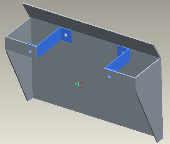
As said it's not to scale but should give you an idea.
#33
slindborg
-
-
- 22,602 posts
The Bishop of Stortford
- Gender:Not Telling
- Location:.
Posted 02 June 2008 - 06:48 PM
that also looks perfect to blow air up to help matters more too
genius 
genius
#34
mandarinvx
-

-
- 12,621 posts
King of First Replies
- Gender:Male
- Location:West Mids / Oxfordshire
Posted 02 June 2008 - 07:09 PM
Is there any chance of bodging a standard tubby one in - not sure if it uses the same of sort of mounting points 
#35
petrolhead1
-

-
- 936 posts
Need to get Out More
- Gender:Male
- Location:Wantage, Oxfordhsire
-
Interests:Windsurfing and Sailing
Karting
My family
Posted 02 June 2008 - 10:36 PM
On Sunday I was talking to VXR36 about some of the issues he had had with heat on his VXT.
He mentioned that his manifold had been ceramic coated ie dipped. Absolutely no idea what this costs or who can do it but that combined with a bigger chimney and some serious heat shielding on the bulkhead had apparently cured the problem. I only say apparently because the car has only back with him a very short while.
Martin just a thought but it might be worth comparing notes with him by PM.
Best of luck and hope you get it sorted and really sorry to have been the bearer of bad news as I seemed to have been the first person to spot the problem.
#36
techieboy
-
-
- 22,914 posts
Supercharger of Doom
- Gender:Male
- Location:Bedford
Posted 02 June 2008 - 11:41 PM
Got a quote of £400 + VAT for ceramic coating on the outside of the manifold only, earlier today!!!!
Shan't be bothering with that, me thinks! More important on Andrews car because of heat issues affecting the turbo. Think I'll fashion something along the lines of Winstar's illustration to protect the bulkhead and maybe line the engine cover above the manifold with some offcuts and maybe duct some air from the offside side vent round into the general area of the manifold (won't help when staionary, unfortunately).
#37
MartinS
-
-
- 5,173 posts
I only bought it for one summer. 14 years ago and now its gone&#
- Gender:Male
- Location:Rustington, West Sussex
-
Interests:Track days
Pubs
Sausages
Posted 03 June 2008 - 05:57 AM
Will see what I can do. I'm no engineer and have no facilities but need something this week, as have a track day soon and its not really driveable now.
What type of bolts do I need to go in the original holes (really wish I had pushed harder to get my original manifold bits back now!).
Martin s
ps Thanks petrolhead. I had noticed some minor problems earlier, but pretty sure a day on the rolling road last Thursday at TMS probably killed it off and I hadnt looked since then.
#38
MartinS
-
-
- 5,173 posts
I only bought it for one summer. 14 years ago and now its gone&#
- Gender:Male
- Location:Rustington, West Sussex
-
Interests:Track days
Pubs
Sausages
Posted 03 June 2008 - 07:00 AM
Hi Winstar
How are you, and thanks for the advice with this.
I'm afraid I cant see the original holes. The new manifold is such a tight fit.
Is it possible to show me where the originals are, if not it may be that I will just fold some nimbus and glue it to the back wall, which would definitely be the easiest method.
Martin
#39
techieboy
-
-
- 22,914 posts
Supercharger of Doom
- Gender:Male
- Location:Bedford
Posted 03 June 2008 - 07:34 AM
Martin, in this picture, the two yellow circles show the location of the upper mounting points. The red circle represents a lower fixing point that was part of the OEM manifold but which we no longer have. There were also two screws in the heat shield that tightened against the manifold at the the merge point to prevent rattles.

#40
Winstar
-
-
- 4,264 posts
Scary Internerd
- Gender:Male
- Location:Chesterfield
Posted 03 June 2008 - 07:58 AM
Martin, in this picture, the two yellow circles show the location of the upper mounting points. The red circle represents a lower fixing point that was part of the OEM manifold but which we no longer have. There were also two screws in the heat shield that tightened against the manifold at the the merge point to prevent rattles.
you beat me to it
That's a better photo, you shouldn't need the lower mounting point as the diagonal sections on the sides and the Z brackets should make it stiff enough not to need it, altough it may be better to leave more sheiding on the side to cover coolant pipes on the left.
As for bolt you'll need 2 that fit in the existing holes then some M5 or M6 stainless nuts and bolts to secure the Z bracket.


1 user(s) are reading this topic
0 members, 1 guests, 0 anonymous users

