Jump to content


Photo

Still No Life.....even After Relay Swap


  • Please log in to reply
88 replies to this topic

#61 vocky

vocky

    Moderator

  • 11,969 posts
  • Gender:Male
  • Location:Earth

Posted 12 April 2015 - 07:23 PM

do you have 12v at pin 86 brown wire - brown relay coil ?


do you have 0v at pin 85 - brown relay coil ?


Sometimes the pins are reversed, that does not matter, what is important is whether you have both the 12v and 0v feeds.


As the relay outputs work okay (when power is manually added to the relay coil and the fact that pin 86 12v feed comes directly from the relay 12v main supply - pin 30) that you are not getting the 0v from the ecu (green/pink wire)


The green/pink wire goes through pin 12 on X2 the blue plug behind the coolant tank (one half of the loom of doom), you should confirm it is coming from the ecu by tapping into the loom before it reaches the X2 plug from the ecu. This will prove if it's the x2 blue plug or the ecu.


Edited by vocky, 12 April 2015 - 07:25 PM.


#62 Arno

Arno

    Need to get Out More

  • PipPipPipPip
  • 1,238 posts
  • Gender:Male
  • Location:Netherlands

Posted 12 April 2015 - 08:01 PM

Until power directed applied, stack still reads 999 and ScanGuage will not connect


Not directly a solution, but perhaps some clues/indications..

The OBD plug data stream on the VX is routed through the immobiliser unit in the steering column and it then relays the data onwards to the ECU.


If the OBD plug is 'dead' then is sounds like the ECU and immobiliser may have lost their handshake/synchronisation or something has damaged the communication between these.


Also the reason why you need to de-pair and re-pair the immobiliser and ECU when swapping ECU's as they won't talk to eachother if they were not 'released' properly.


As for the coolant display.. The ECU generates a plretty plain PWM signal that's sent directly to the STACK for the coolant temperature display. There's nothing inbetween there, just a wiring trace from the engine bay to the STACK via some connectors.


You could at least check continuity between the STACK and the pin on the ECU plug. If there is normal continuity then the ECU is not sending the PWM signal for some reason. I'm not sure, but I don't think the ECU sends 999 if it loses connection to the coolant temperature sender, so most likely this is a wiring break, pin break or ECU fry..


Bye, Arno.


#63 Bargi

Bargi

    Scary Internerd

  • PipPipPipPipPipPip
  • 4,483 posts
  • Gender:Male
  • Location:London

Posted 12 April 2015 - 08:23 PM

We did however manage to get the heap running :
Ignition Off
Brown relay bypassed
Direct 12v feed to :
12V to Pin 86
0v to Pin 85
relay had to be in place
Ignition turned
Fuel pump primed
Stater pressed
Car fired and ran (My new tullet is quite antisocial it turns out!!!!)
temp back to normal briefly
Scanguage connected fine
When feed to relay removed from 12v supply.....car turns off.


Just to confirm, are you saying

- Applied 12 volts direct to 86 on the Brown Fuel Pump Relay and ECU/Stack/everything sprang to life and ran OK?


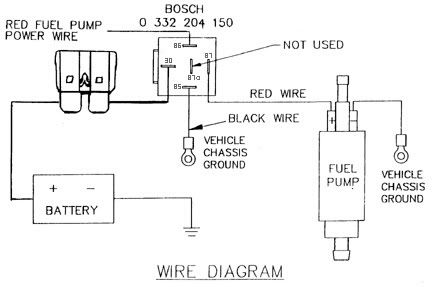
So if the diagram below is correct you put power direct to the relay/86 to activate the pump, but it also would put power back to the ECU wouldn't it? (assuming you still had the wire to the ECU connected)


So is it possible the ECU isn't getting power normally (stack showing 999) and you're now providing power to the ECU back through the fuel pump feed wire?


EDIT: Just read Vockys post now and think I've got it wrong. I took one look at the elec diagrams and my head exploded :)


Posted Image


Edited by Bargi, 12 April 2015 - 08:31 PM.


#64 vocky

vocky

    Moderator

  • 11,969 posts
  • Gender:Male
  • Location:Earth

Posted 13 April 2015 - 08:06 AM

good point Mr Bargi...


if you need to add 12v to make everything work then check fuse FL4, this should be a permanent 12v feed to the brown relay


http://www.speedster...s frame RHD.pdf


#65 cps13

cps13

    Newbie

  • 2 posts
  • Location:United Kingdom

Posted 13 April 2015 - 02:43 PM

Hi 
 
I am the friend with the multi-meter!! We are going to take another crack at this over the next week or so and have a couple of questions for people...
 
 
That circuit diagram put on by Bargi doesn't make sense to me, the "red fuel pump power wire" comes off pin 87 of the relay as shown (high load side), not pin 86. 
 
In my head it isn't a problem with the fuel system, this is my thinking...
 
If you applied 12V to the fuel pump relay (K16) on bench test it fires. 
If you apply 12V to the fuel pump it wines away until you stop it. 
If you apply 12V to the brown relay (K18) then K16 immediately fires. This enabled us to start the car. 
 
I think the problem lies around the wiring for K18. 
 
I have been using this wiring diagram but I cannot get my head around the wiring for K18. http://www.speedster...e Z22SE - 1.pdf
 
If you have a 12V feed directly to pin 86 and pin 30, what is the point in the relay? Why would you not just have a permanent feed via a fuse? As the diagram for K16 shows, it is activated by current from the ECU, this then triggers the load side for the fuel pump. The diagram shows K18 having both the low current and the high current side of the relay connected to a 40A fused circuit, with 0V coming off the ECU, this to me seems odd. 
 
Also, if the FCO switch is on the switched side of the relay, and doesn't go anywhere else, how does this function? 
 
Can anyone tell me what 1001 is on the digram (comes off pin 87 on relay K18). 
 
We tested the feed to the relays, with the ignition on at pins 86 there was a constant 8V (ish, I cannot remember the exact figure). Should this be closer to 12V?
 
Thanks all!! 


#66 vocky

vocky

    Moderator

  • 11,969 posts
  • Gender:Male
  • Location:Earth

Posted 13 April 2015 - 03:03 PM

ignore Bargi's circuit diagram, it's not for a vx220, just a basic fuel pump circuit.


The relay K18 is switched by negative not positive, possibly for an aftermarket immobiliser - so one relay needs positive and one negative, typical immobiliser wiring.


page 2 of engine wiring diagram


http://www.speedster...e Z22SE - 2.pdf


#67 vocky

vocky

    Moderator

  • 11,969 posts
  • Gender:Male
  • Location:Earth

Posted 13 April 2015 - 03:04 PM

1001 is the coilpack and 8v is wrong it must be 12v, you need to check the battery terminals are not corroded as that is where fuse FL4 gets it's feed from.


the fuel cut off will cut power to the fuel pump and is shown on Page 2 of the ecu wiring.


12v power comes from Battery to fuse FL4 to relay K18 (pin 87A) to 'Fuel Cut Off' to K16 (pin 30) - switched by K16 (pin 87) - to fuel pump


Edited by vocky, 13 April 2015 - 03:13 PM.


#68 vocky

vocky

    Moderator

  • 11,969 posts
  • Gender:Male
  • Location:Earth

Posted 13 April 2015 - 03:22 PM

I forgot one thing from that list


12v[color=rgb(40,40,40);font-family:helvetica, arial, sans-serif;] power comes from Battery to fuse [/color]FL4[color=rgb(40,40,40);font-family:helvetica, arial, sans-serif;] to [4 pin connector block near passenger side gearbox mount, has all brown wires, mounted to airbox bracket on most standard airbox cars] to relay [/color]K18[color=rgb(40,40,40);font-family:helvetica, arial, sans-serif;] (pin 87A) to '[/color]F[color=rgb(40,40,40);font-family:helvetica, arial, sans-serif;]uel [/color]C[color=rgb(40,40,40);font-family:helvetica, arial, sans-serif;]ut [/color]O[color=rgb(40,40,40);font-family:helvetica, arial, sans-serif;]ff' to[/color] K16[color=rgb(40,40,40);font-family:helvetica, arial, sans-serif;] (pin 30) - switched by [/color]K16[color=rgb(40,40,40);font-family:helvetica, arial, sans-serif;] (pin 87) - to [/color]fuel pump


Edited by vocky, 13 April 2015 - 03:25 PM.


#69 vocky

vocky

    Moderator

  • 11,969 posts
  • Gender:Male
  • Location:Earth

Posted 13 April 2015 - 03:32 PM

luckily gingerjon took a picture of the plug in question, certainly worth opening it up and spraying with wd40 or electrical cleaner. I have found a bad connection there on a vx  thumbsup


[attachment=26143:plug.jpg]


Edited by vocky, 13 April 2015 - 03:34 PM.


#70 gingerjon

gingerjon

    Super Duper Member

  • PipPipPip
  • 587 posts
  • Gender:Male
  • Location:Hedge End

Posted 04 May 2015 - 07:49 PM

And so, like a cheap series of movies....the Saga continues. Undid, cleaned and reconnected the connector above as Vocky pointed out......still nothing. I have stripped the loom back almost in its entirity in the engine bay and no sign of damaged wires. Ill admit, i didnt have the multimetre so couldnt check the voltage on the wires themselves. This really is dragging on, when do we admit enough is enough and strip it for parts?!?!?! :) Hope everyone had a better Bank Hol and will not be bitter about you all out in your cars!! Nope, not one bit....

Edited by gingerjon, 04 May 2015 - 07:50 PM.


#71 CHILL Gone DUTCH

CHILL Gone DUTCH

    I ADMIT BATMAN THINKS HE IS QUICKER THAN ME

  • PipPipPipPipPipPipPipPip
  • 13,727 posts
  • Gender:Male
  • Location:UK

Posted 04 May 2015 - 07:58 PM

John was the car good before the melting ??

Edited by CHILL Gone DUTCH, 04 May 2015 - 07:58 PM.


#72 gingerjon

gingerjon

    Super Duper Member

  • PipPipPip
  • 587 posts
  • Gender:Male
  • Location:Hedge End

Posted 04 May 2015 - 08:10 PM

Yep,all was working fine until the relay Faux Par. Not had it running properly (without the seperate 12v feed to the relay) since coming to see you to grab the exhaust. Ive replaced so much, all the relays, ECU and Chip set, fuses.... My top tip.....dont leave your relays on the manifold!!!

#73 CHILL Gone DUTCH

CHILL Gone DUTCH

    I ADMIT BATMAN THINKS HE IS QUICKER THAN ME

  • PipPipPipPipPipPipPipPip
  • 13,727 posts
  • Gender:Male
  • Location:UK

Posted 04 May 2015 - 08:13 PM

Is the 12v feed your adding going straight to the pump or on to the permanent/ignition on the relay

#74 gingerjon

gingerjon

    Super Duper Member

  • PipPipPip
  • 587 posts
  • Gender:Male
  • Location:Hedge End

Posted 04 May 2015 - 08:17 PM

onto the wires feeding into/out of the Brown Relay.

#75 CHILL Gone DUTCH

CHILL Gone DUTCH

    I ADMIT BATMAN THINKS HE IS QUICKER THAN ME

  • PipPipPipPipPipPipPipPip
  • 13,727 posts
  • Gender:Male
  • Location:UK

Posted 04 May 2015 - 08:19 PM

So the wire which goes to the pump ??

#76 gingerjon

gingerjon

    Super Duper Member

  • PipPipPip
  • 587 posts
  • Gender:Male
  • Location:Hedge End

Posted 04 May 2015 - 08:26 PM

Yep, held the 12v supply onto it, and them turned the ignition which primed the pump and then it started. Take the 12v off and the car dies. With no 12v supply, the pump doesnt prime when you click the ignition on.

#77 CHILL Gone DUTCH

CHILL Gone DUTCH

    I ADMIT BATMAN THINKS HE IS QUICKER THAN ME

  • PipPipPipPipPipPipPipPip
  • 13,727 posts
  • Gender:Male
  • Location:UK

Posted 04 May 2015 - 08:29 PM

Did you try it on other side of the relay

#78 cps13

cps13

    Newbie

  • 2 posts
  • Location:United Kingdom

Posted 04 May 2015 - 09:18 PM

Did you try it on other side of the relay


the relay has been tested independently and works fine. 


We tested the fuel pump just adding 12V to it and it was fine. 


We added 12V to the low side of the relay in situ and it worked fine. 


I understand what you are saying vocky about FL4 but I think that seeing as it has all stemmed from the melting incident I think the fault probably lies somewhere closer to the relays. We tested the power coming via FL4 and have a clean 12V. Tested the power from FL4 upto the key, turned the key and turn off the immobiliser and 12V switched over as it should do, still clean 12V. Followed it back as far as possible until it got lost within chassis. Then ran out of time to test much more. 


I think we need to figure out why there is not 12V at the relay. I would assume a short somewhere, does anybody know the current you would expect to see? 


Edited by cps13, 04 May 2015 - 09:22 PM.


#79 gingerjon

gingerjon

    Super Duper Member

  • PipPipPip
  • 587 posts
  • Gender:Male
  • Location:Hedge End

Posted 12 May 2015 - 06:59 PM

Shameless Mid Week bump :blush: .....having another go on this at the weekend, advice so far has been really helpful in eliminating potential issues. Any further "Eureka" moments anyone has, please feel free to let me know.


Thanks everyone  :grouphug: Really appriciated. Imnotworthy


GJ


#80 vocky

vocky

    Moderator

  • 11,969 posts
  • Gender:Male
  • Location:Earth

Posted 12 May 2015 - 08:32 PM

check whether you have 12v at the four pin plug pictured in my post above, then measure the resistance of the cable from the relay to that plug.


Or unwrap the loom between the relay and that plug and look for the burn't out wire


Edited by vocky, 12 May 2015 - 08:32 PM.


0 user(s) are reading this topic

0 members, 0 guests, 0 anonymous users