answering my own question - an na


Future of Speed


Posted 03 December 2014 - 09:57 AM
answering my own question - an na
Member
Posted 03 December 2014 - 10:09 AM
Sorry mate missed ur questionanswering my own question - an na
Future of Speed
Posted 03 December 2014 - 10:48 AM
No worries keep buildingSorry mate missed ur questionanswering my own question - an na

Need to get Out More

Posted 03 December 2014 - 04:04 PM

Will keep popping back to see progress!
Need to get Out More

Posted 03 December 2014 - 06:08 PM
Some pics of the lower mounts...
You might want to consider using a significantly bigger diameter (solid) rubber mount for these on the chassis and subframe end. (there's lots of space to go at least as big as the OEM one..)
That would allow you to run a slightly softer rubber compound (but still solid) and keep some compliance mainly to dampen out annoying 'buzzy' vibrations at idle and some spots in the rpm range. As long as it's a solid rubber one it should keep larger engine movements in check.
The current small diameter ones will probably need to be quite hard (or even PU bushes) to survive the forces put onto them and it can result in a quite an annoyingly rattly/buzzy car.
The gearbox one can probably also do with another brace bar welded onto it from the subframe bush to the rearmost point on the gearbox attachment to create a tension/compression element to stop the current bar breaking at the welds or bending as the engine wants to rotate.
Some extra gussets and cross-braces on the main engine mounts may be good too.
Bye, Arno.
Member
Posted 04 December 2014 - 07:54 PM
Thanks for the advice Arno weve taken it on board. Were going to add some more bracing and gussets on the mounts but for the moment stay with the pu bushings and maybe look at them at a later date if we find the vibration is too much.... on the lower mounts did you mean add another brace so theyre triangulated rather than being single straight joints?
Some pics of the lower mounts...
You might want to consider using a significantly bigger diameter (solid) rubber mount for these on the chassis and subframe end. (there's lots of space to go at least as big as the OEM one..)
That would allow you to run a slightly softer rubber compound (but still solid) and keep some compliance mainly to dampen out annoying 'buzzy' vibrations at idle and some spots in the rpm range. As long as it's a solid rubber one it should keep larger engine movements in check.
The current small diameter ones will probably need to be quite hard (or even PU bushes) to survive the forces put onto them and it can result in a quite an annoyingly rattly/buzzy car.
The gearbox one can probably also do with another brace bar welded onto it from the subframe bush to the rearmost point on the gearbox attachment to create a tension/compression element to stop the current bar breaking at the welds or bending as the engine wants to rotate.
Some extra gussets and cross-braces on the main engine mounts may be good too.
Bye, Arno.
Edited by vxt5, 04 December 2014 - 07:57 PM.
Nipper's Minion

Posted 05 December 2014 - 08:56 AM
This is impressive stuff VXT5
Where abouts in South Wales are you? I drive over from Bristol to the Black Mountains quite a bit on good weekends, I'd love to pop over and take a butchers at your work and have a chinwag if you fancy it.
What's your day job, are you some sort of fabricator/mechanic, as you seem to know exactly what your doing.
Edited by Nev, 05 December 2014 - 08:57 AM.
RaceMode

Posted 05 December 2014 - 09:12 AM
thats a nice picture of the inside of the subframe leg , its a lot weaker than it looks.
Scary Internerd

Posted 05 December 2014 - 12:27 PM
Yep, experienced this first hand recently.. :-/thats a nice picture of the inside of the subframe leg , its a lot weaker than it looks.
Need to get Out More
Posted 05 December 2014 - 04:12 PM
on the lower mounts did you mean add another brace so theyre triangulated rather than being single straight joints?
Indeed.. To make sure the rotation movement of the engine when it's putting down power does not start to bend the tube (or break the welds) between the subframe end and the first connection to the gearbox.
The front one should be less of an issue as far as bending goes as it only has 1 attachment point on the engine and chassis.
It may want to rotate though and perhaps loosen the bolt that attaches it to the engine. If that's an issue then perhaps use the second bolt hole you see on the photo to link onto and provide an anti-rotation 'anchor' like you already have on the rear/gearbox mount as well.
It then may also need some triangulation or postitive interlock so you don't have to rely only on the weld(s) to keep it attached.
BTW.. May want to consider doing these lower mounts cut from steel plate with only the bush attachment welded on like a tube.
Something like this (just as an example):
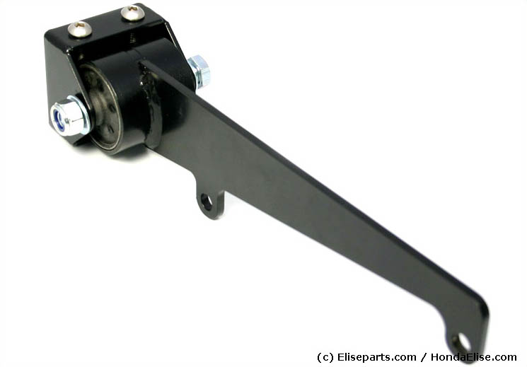
The single-piece steel plate will be very strong in the direction the forces work on it and there's not much that can break off or bend.
Just need to find someone with a laser/water/plasma cutter and a CNC control
Anyway.. Perhaps that's for 'phase 2'. The ones you have should work too, just keep an eye on them for possible breakage/bending and re-design when needed... That's part of the development process! 
Bye, Arno.
Member
Posted 05 December 2014 - 10:27 PM
Understood arno thanks for the helpon the lower mounts did you mean add another brace so theyre triangulated rather than being single straight joints?
Indeed.. To make sure the rotation movement of the engine when it's putting down power does not start to bend the tube (or break the welds) between the subframe end and the first connection to the gearbox.
The front one should be less of an issue as far as bending goes as it only has 1 attachment point on the engine and chassis.
It may want to rotate though and perhaps loosen the bolt that attaches it to the engine. If that's an issue then perhaps use the second bolt hole you see on the photo to link onto and provide an anti-rotation 'anchor' like you already have on the rear/gearbox mount as well.
It then may also need some triangulation or postitive interlock so you don't have to rely only on the weld(s) to keep it attached.
BTW.. May want to consider doing these lower mounts cut from steel plate with only the bush attachment welded on like a tube.
Something like this (just as an example):
The single-piece steel plate will be very strong in the direction the forces work on it and there's not much that can break off or bend.
Just need to find someone with a laser/water/plasma cutter and a CNC control
Anyway.. Perhaps that's for 'phase 2'. The ones you have should work too, just keep an eye on them for possible breakage/bending and re-design when needed... That's part of the development process!
Bye, Arno.
Member
Posted 05 December 2014 - 10:42 PM
Member
Posted 05 December 2014 - 10:44 PM
on the lower mounts did you mean add another brace so theyre triangulated rather than being single straight joints?
Indeed.. To make sure the rotation movement of the engine when it's putting down power does not start to bend the tube (or break the welds) between the subframe end and the first connection to the gearbox.
The front one should be less of an issue as far as bending goes as it only has 1 attachment point on the engine and chassis.
It may want to rotate though and perhaps loosen the bolt that attaches it to the engine. If that's an issue then perhaps use the second bolt hole you see on the photo to link onto and provide an anti-rotation 'anchor' like you already have on the rear/gearbox mount as well.
It then may also need some triangulation or postitive interlock so you don't have to rely only on the weld(s) to keep it attached.
BTW.. May want to consider doing these lower mounts cut from steel plate with only the bush attachment welded on like a tube.
Something like this (just as an example):
The single-piece steel plate will be very strong in the direction the forces work on it and there's not much that can break off or bend.
Just need to find someone with a laser/water/plasma cutter and a CNC control
Anyway.. Perhaps that's for 'phase 2'. The ones you have should work too, just keep an eye on them for possible breakage/bending and re-design when needed... That's part of the development process!
Bye, Arno.
Understood arno thanks for the help will add more pics once weve hopefully finished the mounts
Member
Posted 07 December 2014 - 10:24 PM


Wannabe....

Posted 08 December 2014 - 06:22 AM
Need to get Out More
Posted 08 December 2014 - 09:00 AM
Nice to see how incredibly compact/short the Volvo 6-speed gearbox is.. 
BTW.. This would be the perfect time to replace the clutch so you're sure to start out with an 'as new' setup
Bye, Arno.
Scary Internerd

Posted 08 December 2014 - 08:07 PM
I'm about to do something similar with my hubs. What paint did you use as that looks perfect.
small update. Give the rear hubs a clean and a lick of paint with new bearings. Going to do the same with the arms and replace all joints and bushings.
Member
Posted 08 December 2014 - 08:37 PM
Not painting it as such. just giving it a light dusting to clean it up a bit. Ive taken pretty much everything external off the engine so that I dont have to worry about getting overspray on them and they will all be remaining the standard colourWhy paint it? You will have issues with paint matching when something needs to be replaced. Genuine question, not trying to be an ass.
Member
Posted 08 December 2014 - 08:43 PM
Nice to see how incredibly compact/short the Volvo 6-speed gearbox is..
Member
Posted 08 December 2014 - 08:47 PM
I tried everything when cleaning up my hubs. Used abrasive wheels...wire brushes and a diy sandblaster.... it takes more elbow grease than anything else and for paint I just used gold hammerite...I'm about to do something similar with my hubs. What paint did you use as that looks perfect.
Also, did you sandblast before hand?


0 members, 2 guests, 0 anonymous users


